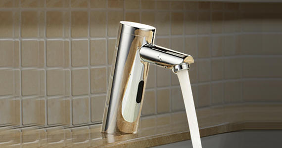
Installation Instructions for Rio Goose Neck Hands Free Commercial Automatic Brushed Nickel Faucet | BSTHD511DC-BN
Reduces the transfer of germs by preventing cross-contamination and re-contamination of germs and bacteria by not touching the faucets or handles.Cut down on water usage by minimizing waste of water while soaping, lathering, scrubbing and drying hands by eliminating unnecessary and unattended water flow.
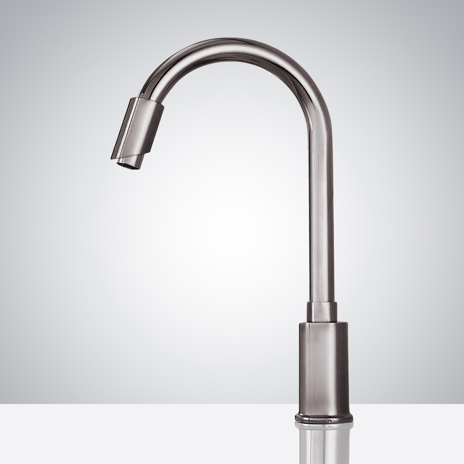
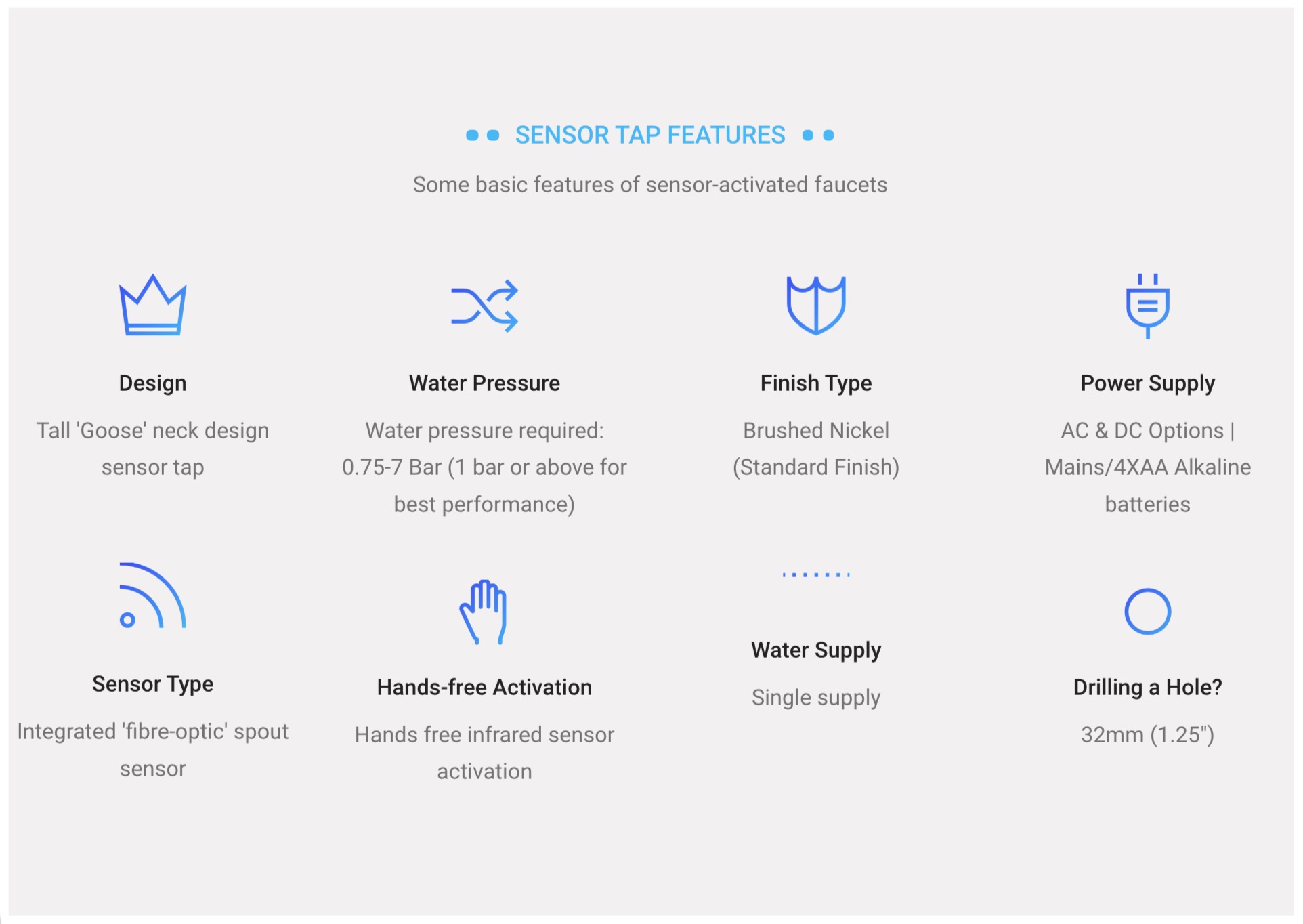
Intelligent: with its micro-computer controlling its action, the faucet can self adjust its best detection zone as per the color and shape of lavatory!Sensor Faucet finish is brushed nickel, with built-in Infrared AI Smart-Chip No Water Dripping Design 100% Touch-free operation.
Features:
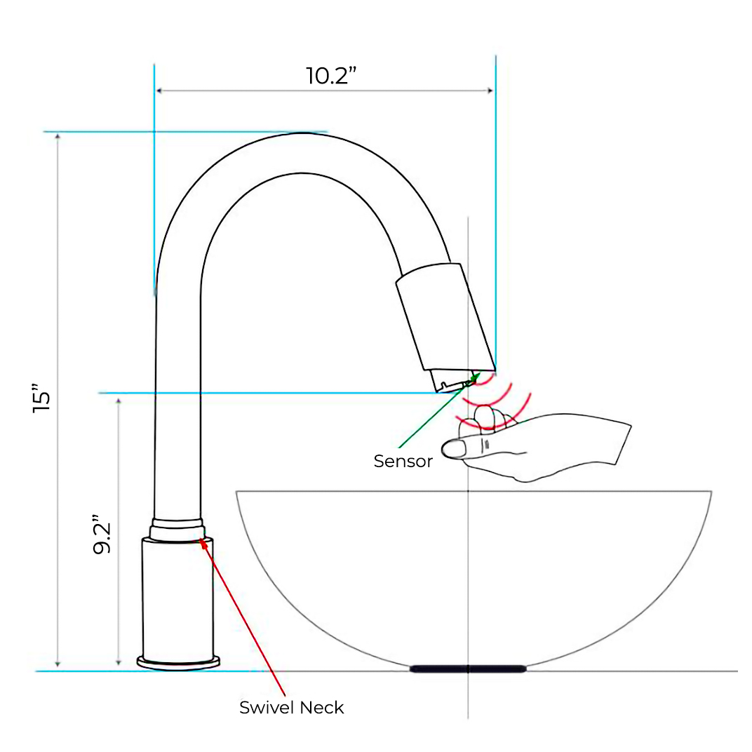
Overall Height: 11- 1/2" (measured from countertop to the highest part of the faucet)
Spout Height: 7-3/4" (measured from counter top to the spout outlet)
Spout Reach: 5-1/2" (measured from the center of the faucet base to the center of spout outlet)
Mounting Type: Single hole
Number of Hole Required for Installation: 1
Flow Rate: 1.3 GPM (gallons-per-minute)
Maximum Deck Thickness: 1-5/8"
Infrared sensor operation
Faucet Body Material: Brass
Faucet Spout Material: Brass
sensor faucet
Important Note:
Before you begin, please read the installation instructions below. Observe all local building and safety codes.
Unpack and inspect the product for any shipping damages. If you find damages, do not install.
Please note all showers must be installed by a professional and certified plumber otherwise warranty may be voided.
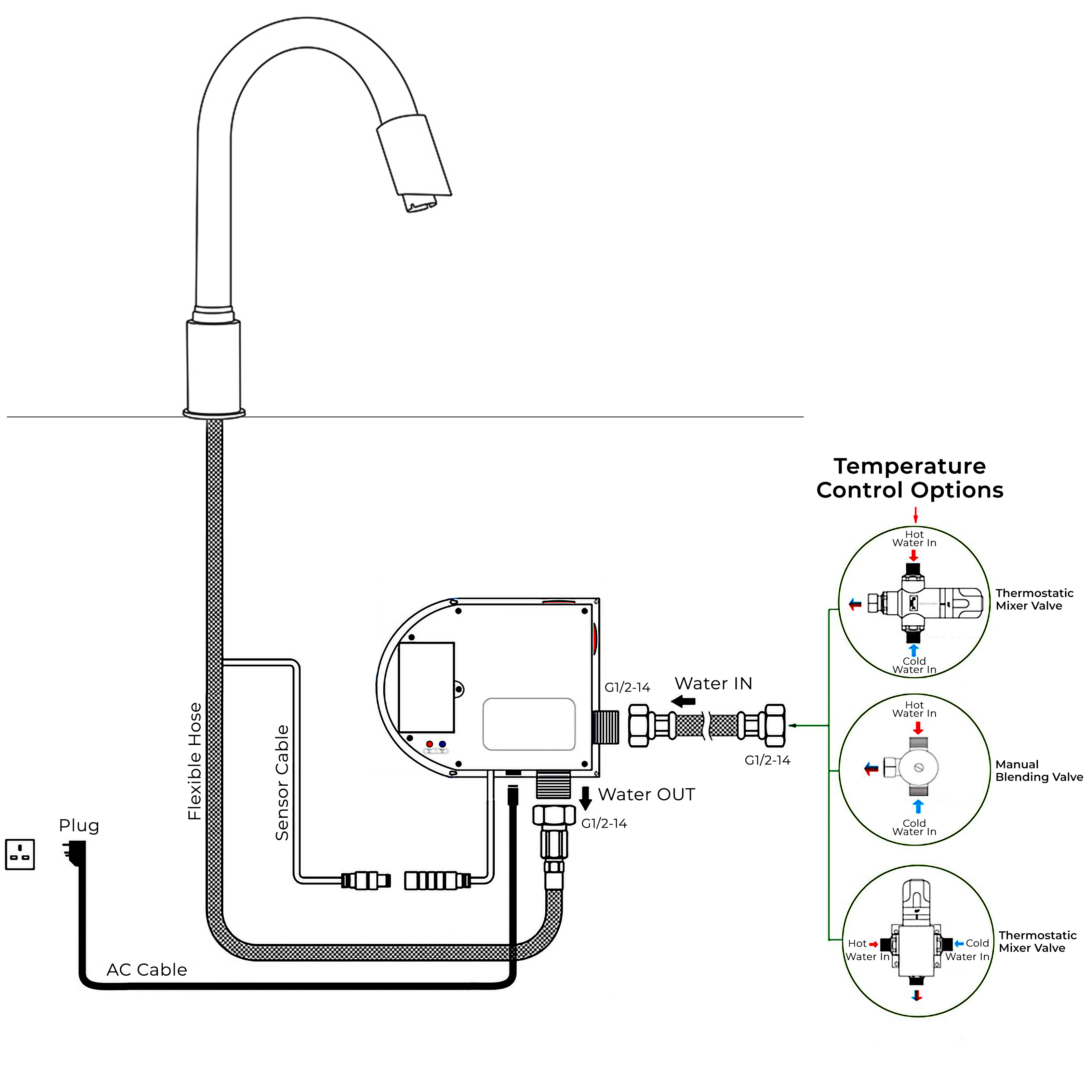
Sensor Faucet Installations Instructions
Size:
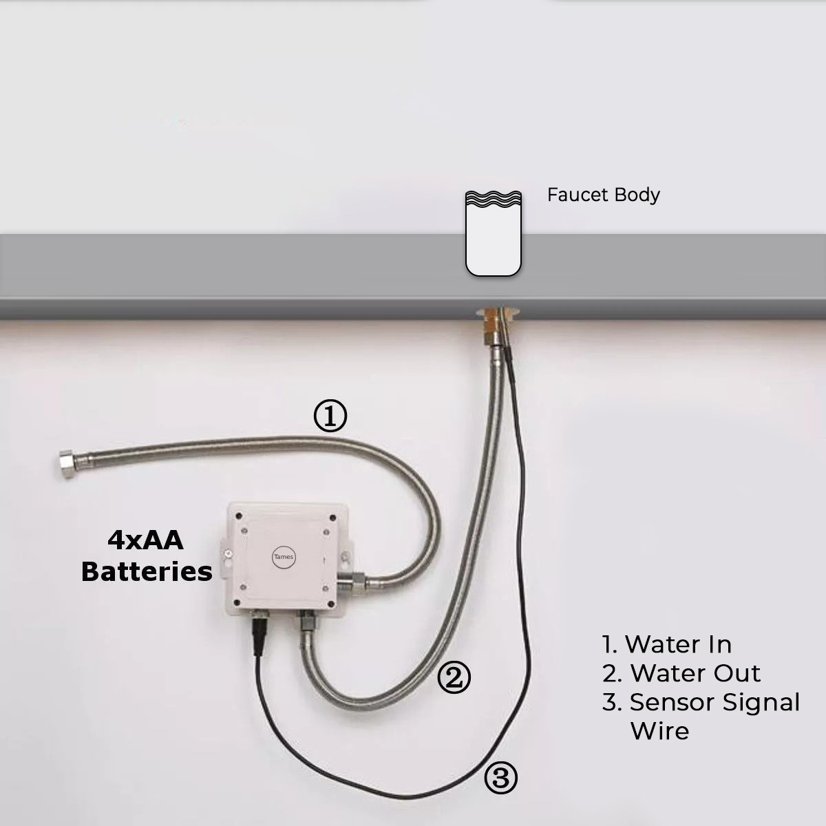
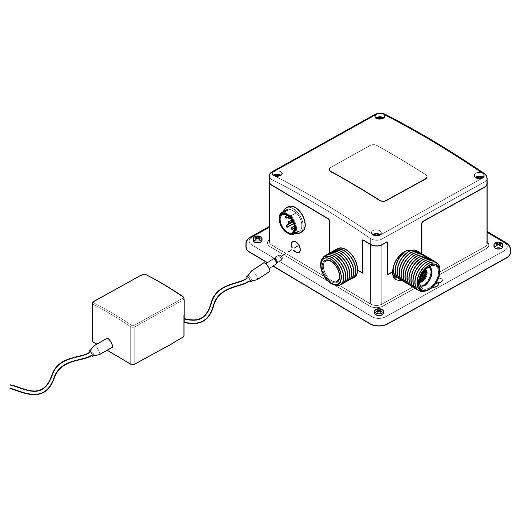
Battery (DC 6V) Only Control Box
Step 1:
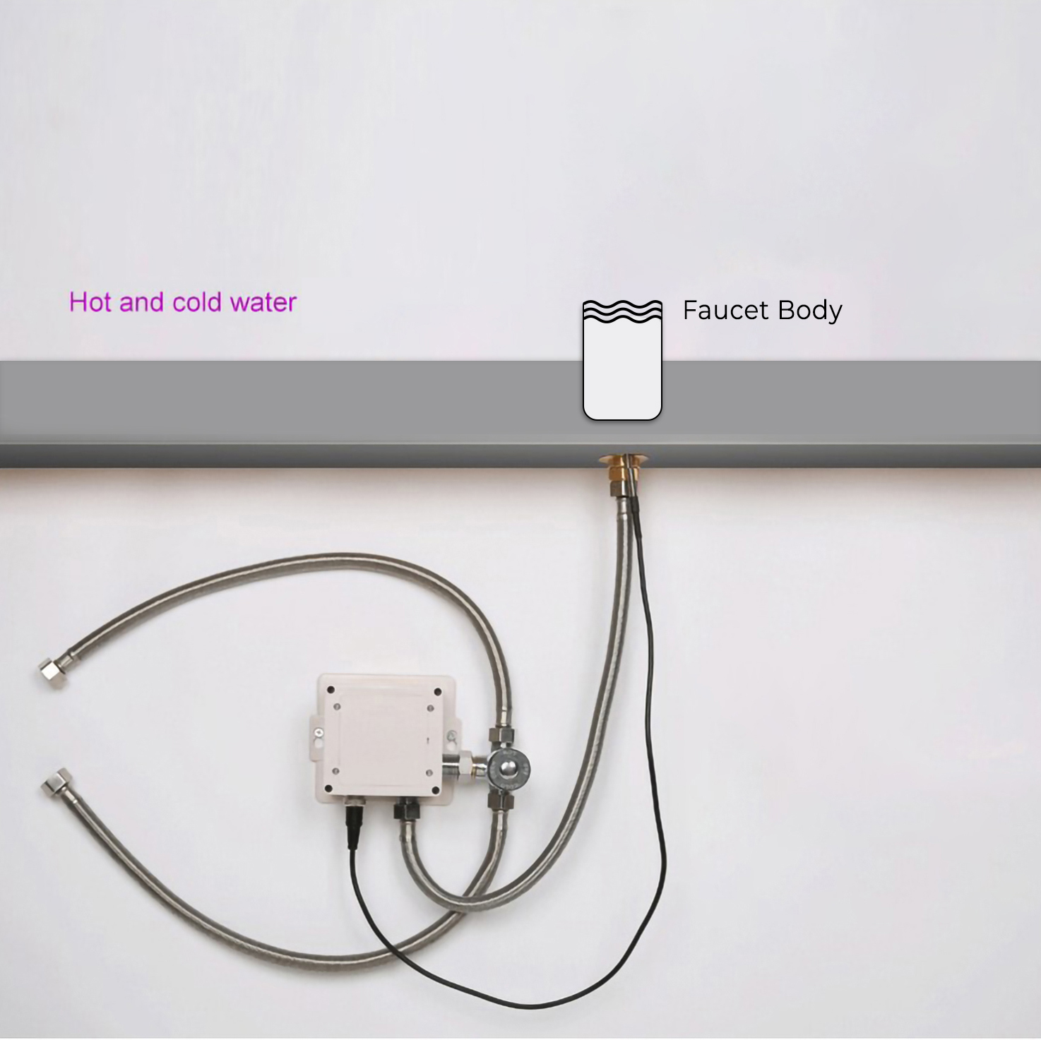
Step 2: (Hot & Cold Connection)
infrared
Battery (DC 6V) & AC 220V Control Box
Step 3:
Step 4:
Step 5: (Flush debris from waterpipes)
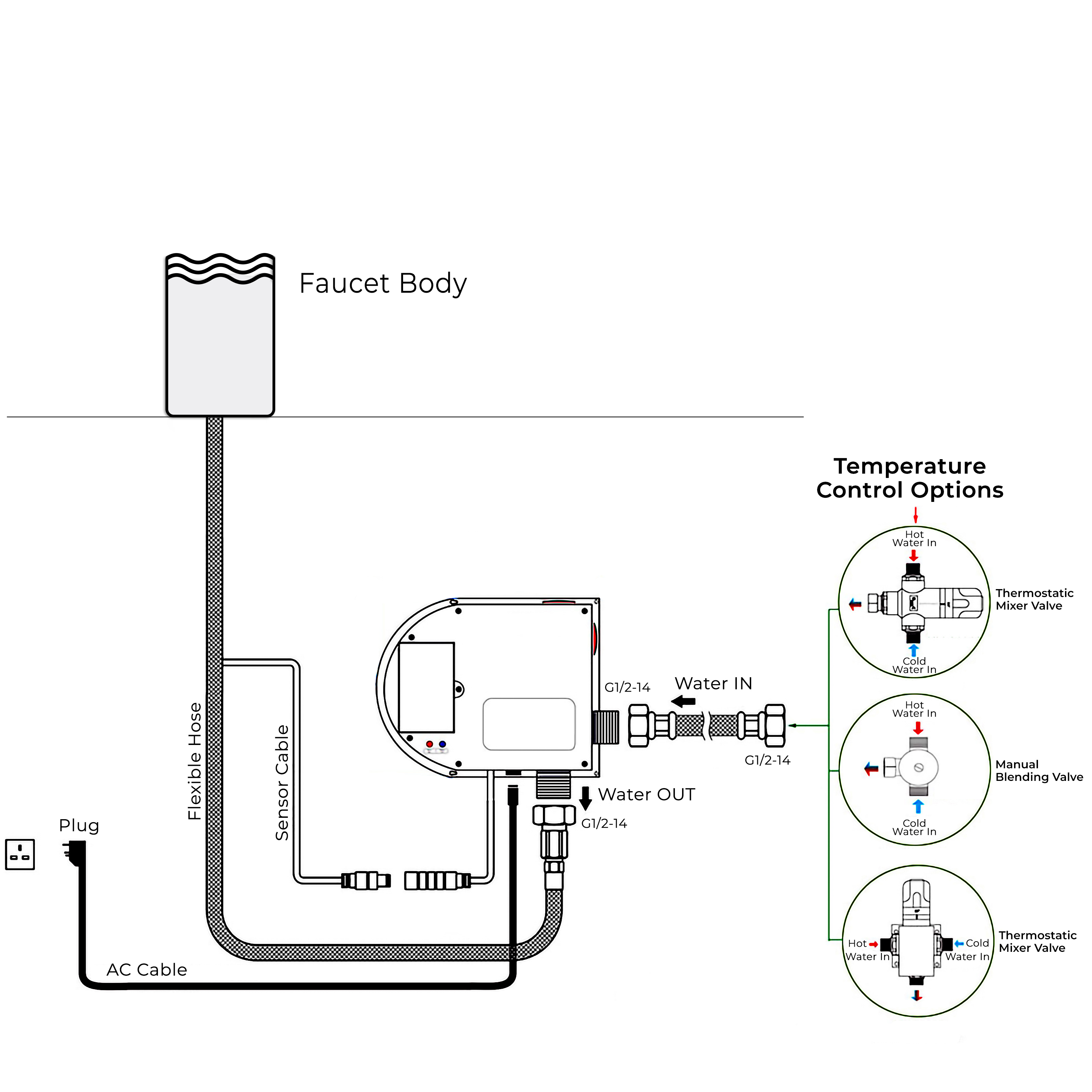
Step 6: Hot & Cold Regulator
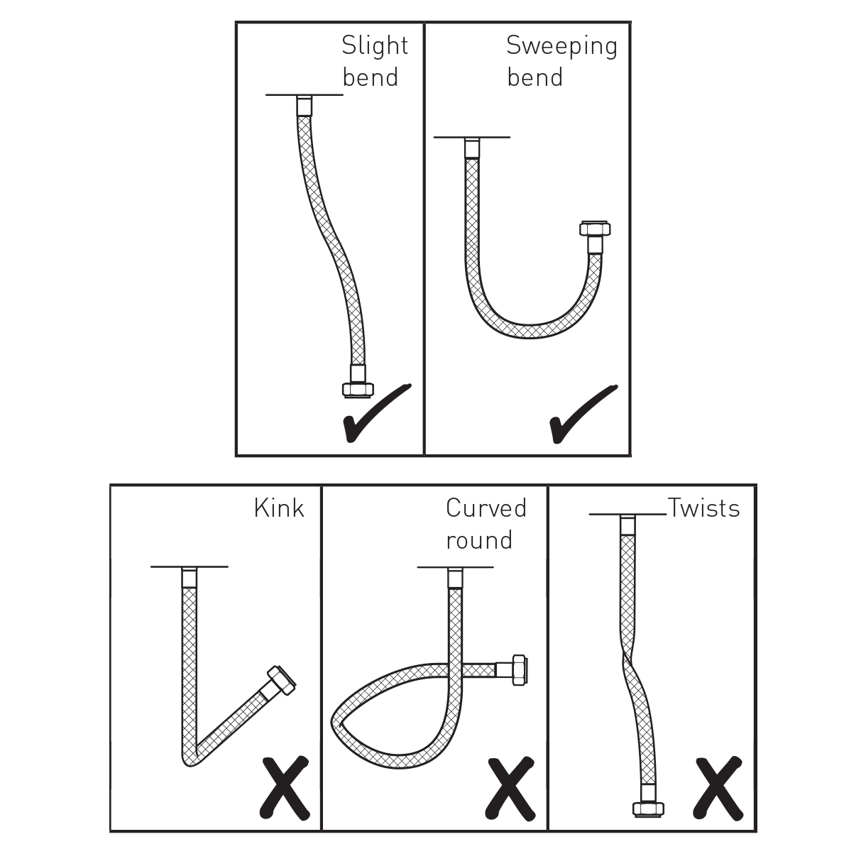
Step 7: (Correct way for Hose)
1. Screw the hose into the corresponding screw-hole of the faucet body. Fix the o-ring into the bottom groove of the faucet body.
2. Insert hose, threaded pipe and data cable through the drilled hole of the countertop. Put rubber washer and metal washer onto the threaded pipe, screwing in mounting nut. Adjust the faucet body correctly and tighten the mounting nut with screws.
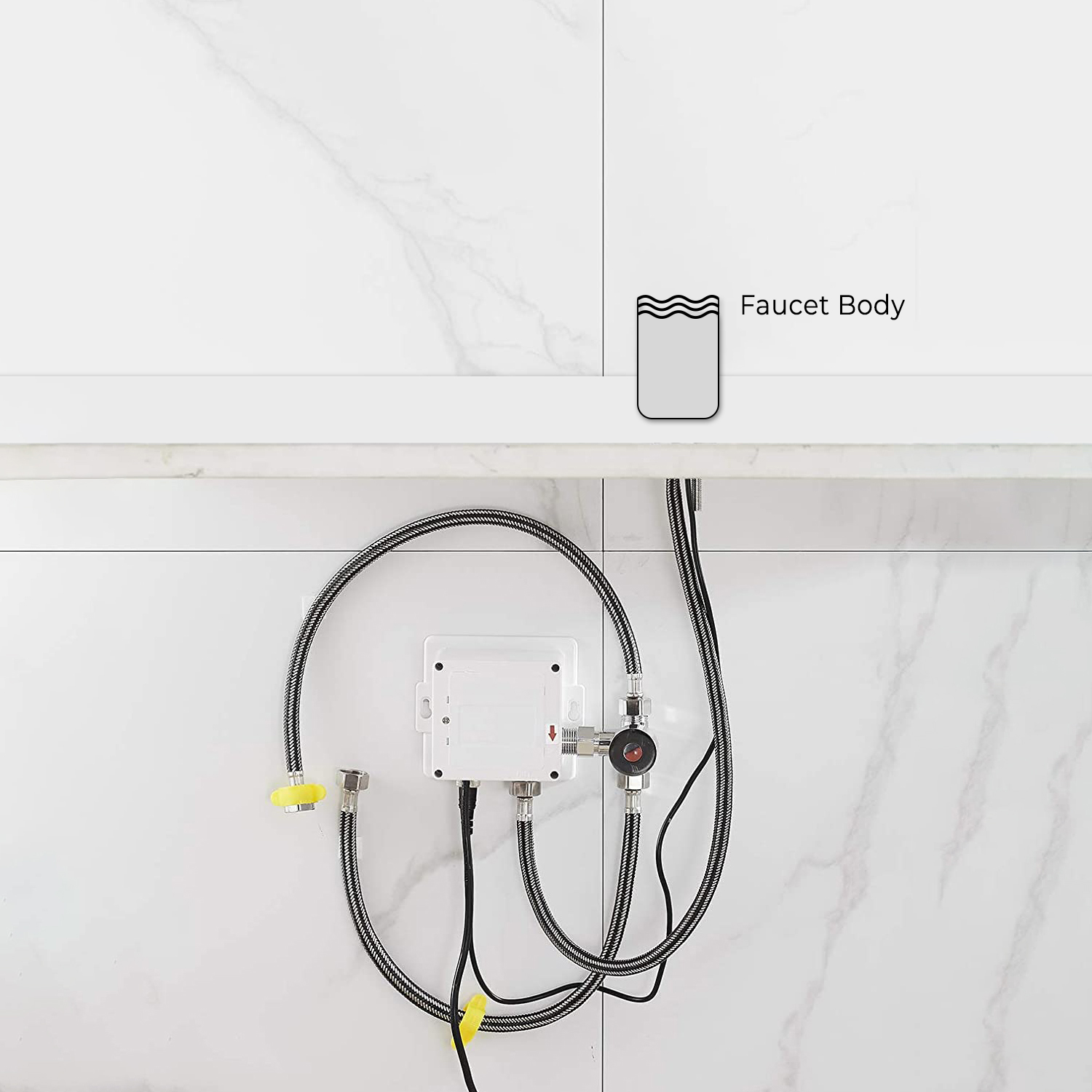
3. Install the control box to the wall and fix it with screws.
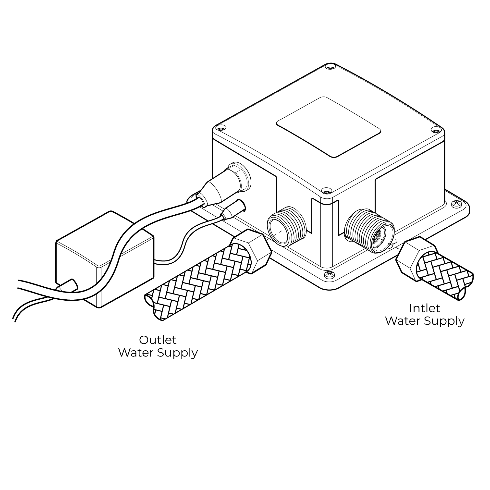
4. Add the rubber washer and screw supply elbow to the control box.
5. Add rubber washers and connect water lines to the hot and cold inlets of the supply elbow. Then connect the hose to the water outlet and insert data cable into the control box and plugin.
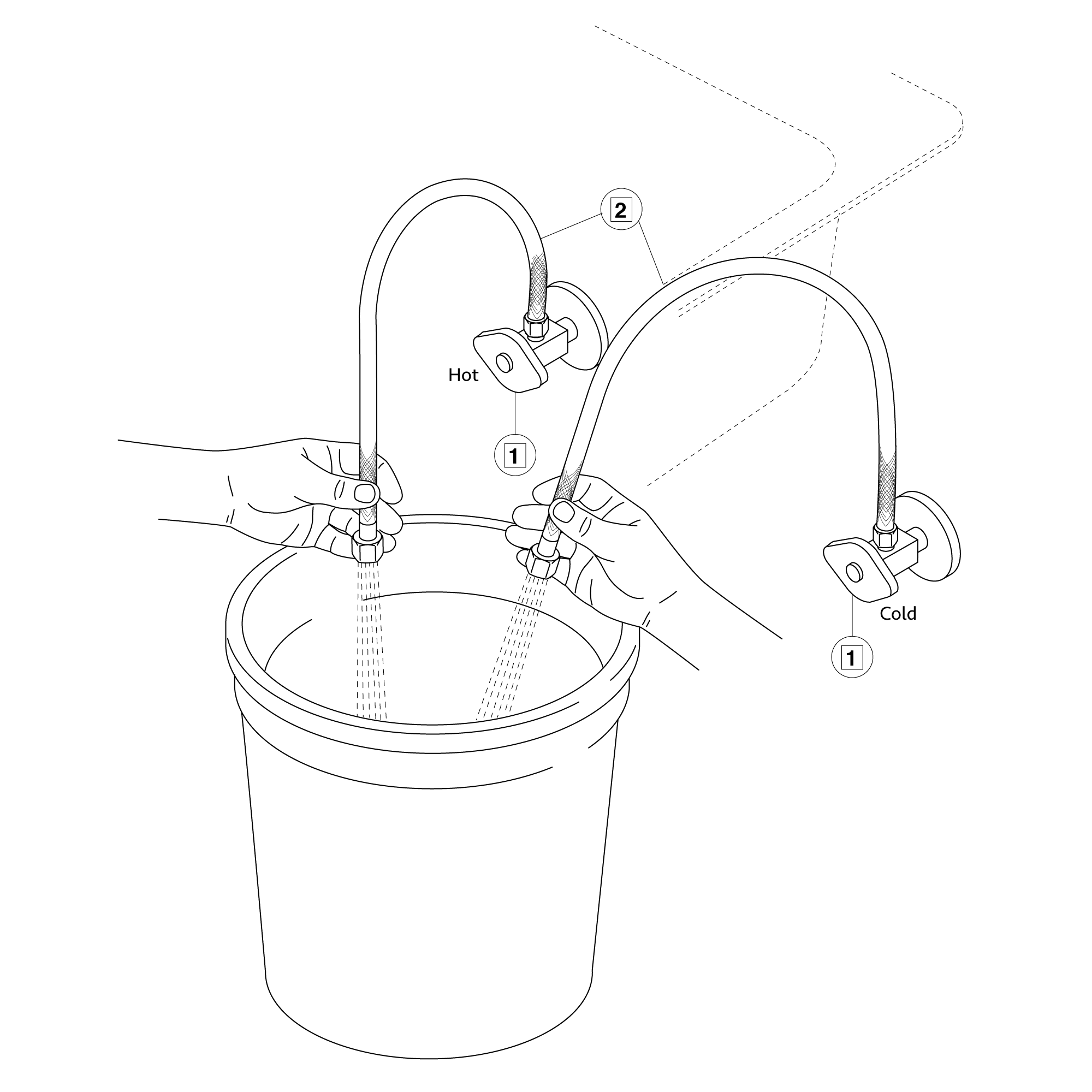
6. Make Connections to water supplies. Turn on hot and cold water supplies and flush water lines into a container for one minute. Important: This flushes away any debris that could cause damage to internal parts.
7. Connect waterlines to angle stops. Turn on the angle stops and check for leaks (DO NOT TURN FAUCET ON).
8. Turn the faucet on for 1 minute to flush any debris.
Flexible Connecting Hose Care must be taken when connecting the flexible connection hose from the power supply box to the spout to ensure it does not bend sharply and kink or twist. See above for recommended ways to fit the flexible connecting hose.
Important: Failure to follow these guidelines may result in poor performance and damage to the flexible connection hose.
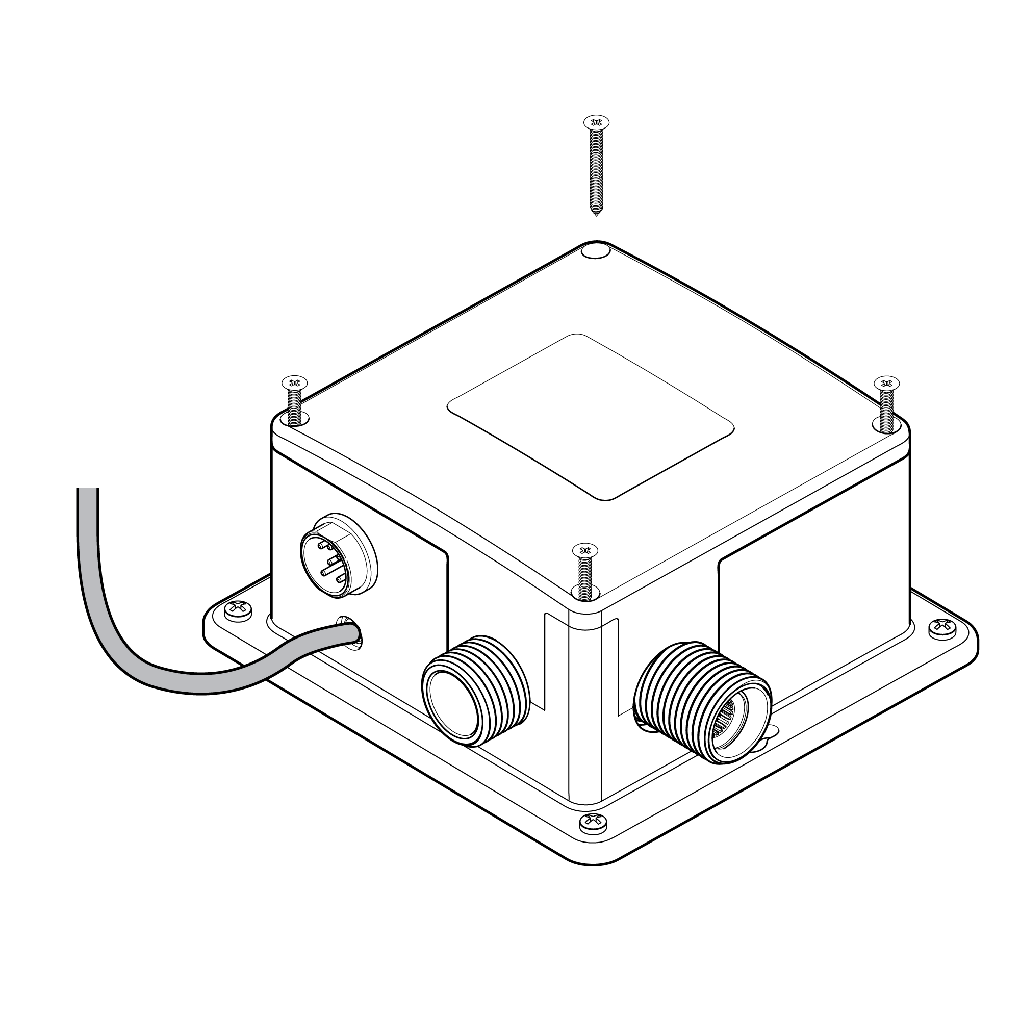
Control Box Installation Instructions
Step 1:
Step 2:
control box
Step 3:
Step 4:
Size: 5" x 5"
AC Cable
Step 5:
Step 6:
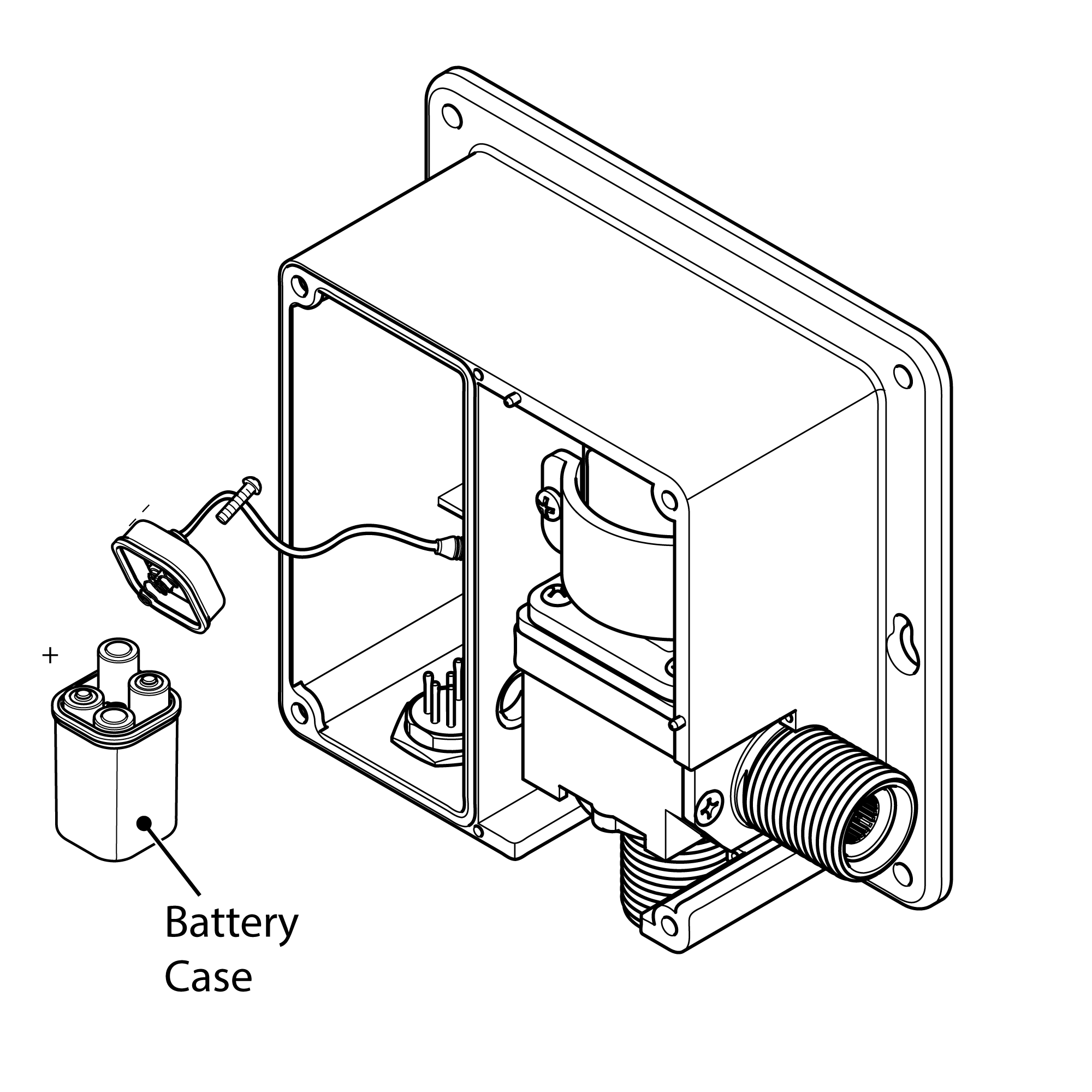
Inserting Batteries Your infrared spout is supplied with a back up battery pack (batteries not included). In the event of a power failure the batteries will override the mains power supply to ensure the spout continues to function.
Before fitting the power supply box into position on the wall/floor, batteries (not included) will need to be fitted.
1. Remove Power Supply Box Cover Remove all four screws in each corner of the power supply box and remove the cover.
2. Remove Battery Box Remove the battery case from the power supply box and remove the screw in the center of the case.
3. Insert Batteries Insert 4 x AA batteries (not included) into the battery box ensuring they are inserted the correct way. Note: Only use 1.5V AA (LR6) Alkaline batteries (preferably => 2000mAh for good battery life).
4. Replace Battery Box Replace the battery case cover. Replace and tighten the screw. Insert the battery case back into the power supply box.
5. Replace Power Supply Cover Replace the power supply cover and tighten all 4 screws ensuring they are all fully tightened.
Installation - Electrical Connections
1. Position Power Supply Box Position the power supply box onto the wall surface below the sink/work surface where it is easily accessible.
Note: Ensure that the power supply box is fitted the correct way up (see opposite) and that the flexible hose will reach from the underside of the spout to the power supply box.
Using suitable fixings for the wall type secure the power supply box to the wall.
2. Connect Power Supply Cable Before starting any electrical work ensure the power supply is isolated. Wire the electrical power cable into a switched fused spur off the ring main. The blue wire should be wired to the neutral connection and the brown wire should be connected to the live connection.
Important: The power supply box must be permanently connected to the fixed wiring of the mains supply using the factory supplied power cable.
3. Plug In Power Cable Plug the power cable into the power supply box.
4. Connect The Sensor Cable Plug the sensor cable from the spout into the power supply box to activate the infrared senor.
Installation - Water Connections
Connecting Water Supply A blended water supply is required to the inlet of the power supply box. Before connecting the water supply to the power supply box flush through the pipework to ensure removal of debris. Once flushed through turn off the mains water supply and close any isolating valves.
Inlet Connection The inlet connection on the power supply box is a 1/2 BSP male threaded connection. Connect a 1/2 BSP female connector to the inlet connection ensuring a suitable sealing washer is used to create a water tight connection.
Outlet Connection The outlet connection is a standard 1/2 BSP male threaded connection. Connect the flexi hose (supplied) to the outlet connection, ensuring it is tightened fully.
Specs:
Inlet pipe diameter: DN15
Outlet pipe diameter: DN15
Water pressure: 0. 05Mpa - 0.7Mpa
DC.6V of power and voltage
AC.220V - 50 / 60Hz
Power consumption 0.5MW
Factory set detection zone 25cm (based on standard inductive joint)
Ambient temperature: 1-45 ºC
Enclosing protection degree 1 P 56
Features:
1. Infrared sensor operated, touch-free operation
2. Advanced design for long battery life energy saving
3. waterproof sensor
4. low battery indicator light
5. automatically adjusted sensing distance
6. Long life durable body
7. Advanced circuit design saves electricity and water
8. Battery: 4 * 'AAA' size cells
9. Operational water pressure range: 0.05 - 0.6MPa
10. Water supply size: DN15
11. Temperature: 0.1 - 45 degrees
12. Detection distance: 20cm factory set
13. Delay time: 0.5 seconds
14. Operation duration: Power will automatically cut off after continuous use for 60 seconds
Function:
1. Water saving: water flows out when hands get close and stops immediately.
2. Hygienic: one open and close to hands-free from any contact, which can efficiently prevent mutual infection of bacteria
3. Intelligent: with your computer to control its action, the faucet can auto adjust its best detection zone as per color and the shape of the sink
4. Low power consumption: for DC agitators, 4AA alkaline batteries can be used for 2 years.
5. convenient to maintain: there is an internal filter to prevent the entry of the solenoid valve of miscellaneous and the filter is easy to clean