Installation Instructions for Melo Automatic Commercial Sensor Brushed Nickel Faucet (Also Available In Oil Rubbed Bronze Or Gold Finish) | BST501-B
| Sensor Activated Faucet Special Features: Intelligent: with its micro-computer controlling its action, the faucet will self adjust its best detection zone as per the color and shape of lavatory Low power consumption: 4AA alkaline batteries can be used for 2 years at 200 cycles a day Convenient to maintain: Built-in strainer prevents sundries from entering the solenoid valve and the strainer is easy to clean. |
|

|
|
Features:
|
|
Visit Product Page 
|
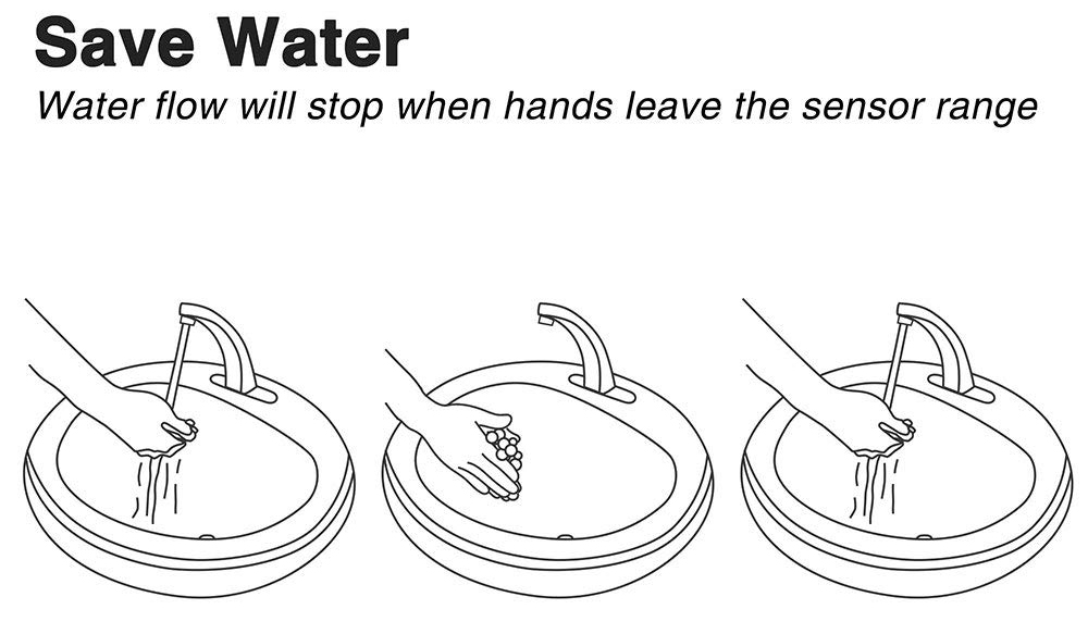
- Sensor faucet complete motion detection operation.
- Sensitive Sensor with Infrared AI Smart-Chip
- Factory set to 30-second Auto Shutoff (can be adjusted).
- Water Pressure: 0.5 - 7.0 KGS/cm , 10 - 125 psi
- Solid Brass Construction, Brushed Nickel Finish
- Easy to Install - Instructions Included
- Water resistant solenoid enclosure
- Advanced energy saving design for long lasting battery life
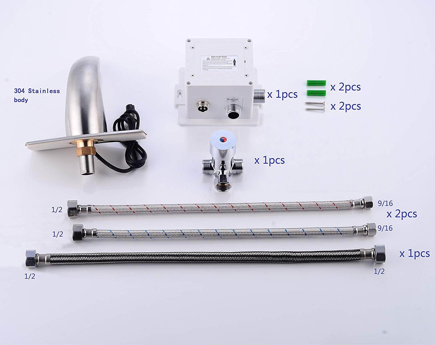
- Comes complete with Hoses & Accessories
- Power Supply: AC110V And DC6V (batteries not included)
- AC/DC power option.
- ADA Compliant
- Easily can be installed in new or retrofit applications.
- Usage: Commercial / Residential
| sensor faucet
|
 Installation.jpg)
|
Important Note:
Before you begin, please read the installation instructions below. Observe all local building and safety codes.
Unpack and inspect the product for any shipping damages. If you find damages, do not install.
Please note all products must be installed by a professional and certified plumber otherwise warranty may be voided.
|
|
Sensor Faucet Installations Instructions
|
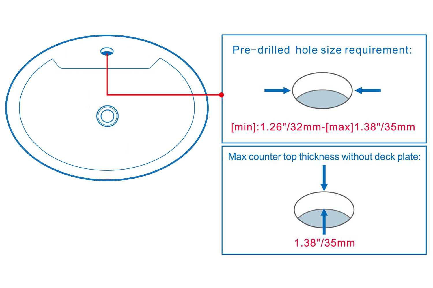
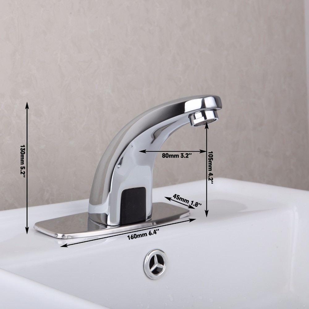
Size:
|
|
Hole Size Chart: |
|
sensor |

|
Description:
- Type: Basin faucets
- Faucet Mount: Single Hole
- Style: Contemporary
- Feature: Sense Faucets
- Number of Handles: none
- Installation Type: Deck mounted
- Valve Material: Electrovalve
- Type: automatic faucet
- Material: brass faucet body, ABS plastic electrical control box, waterproof and moisture-proof
- Craft: five-layer galvanized, three-layer polish
Function:
- Patent hydropower technology, safety and environmental protection
- Fashion colorful panels to match preferences for different groups of people
- Long spool life through 500,000 times life test
- High standard plating, wear-resistant panels, appearance is always brilliant, beautiful, bright clean like new
Specifications:
- Sensor range: 15-18 cm
- Water pressure: 1-6 bar
- Induction time: 1-3 seconds
- Ambient temperature 0.1-45 degrees
| | | | Deck Mount Installation | |
|  | sensor | 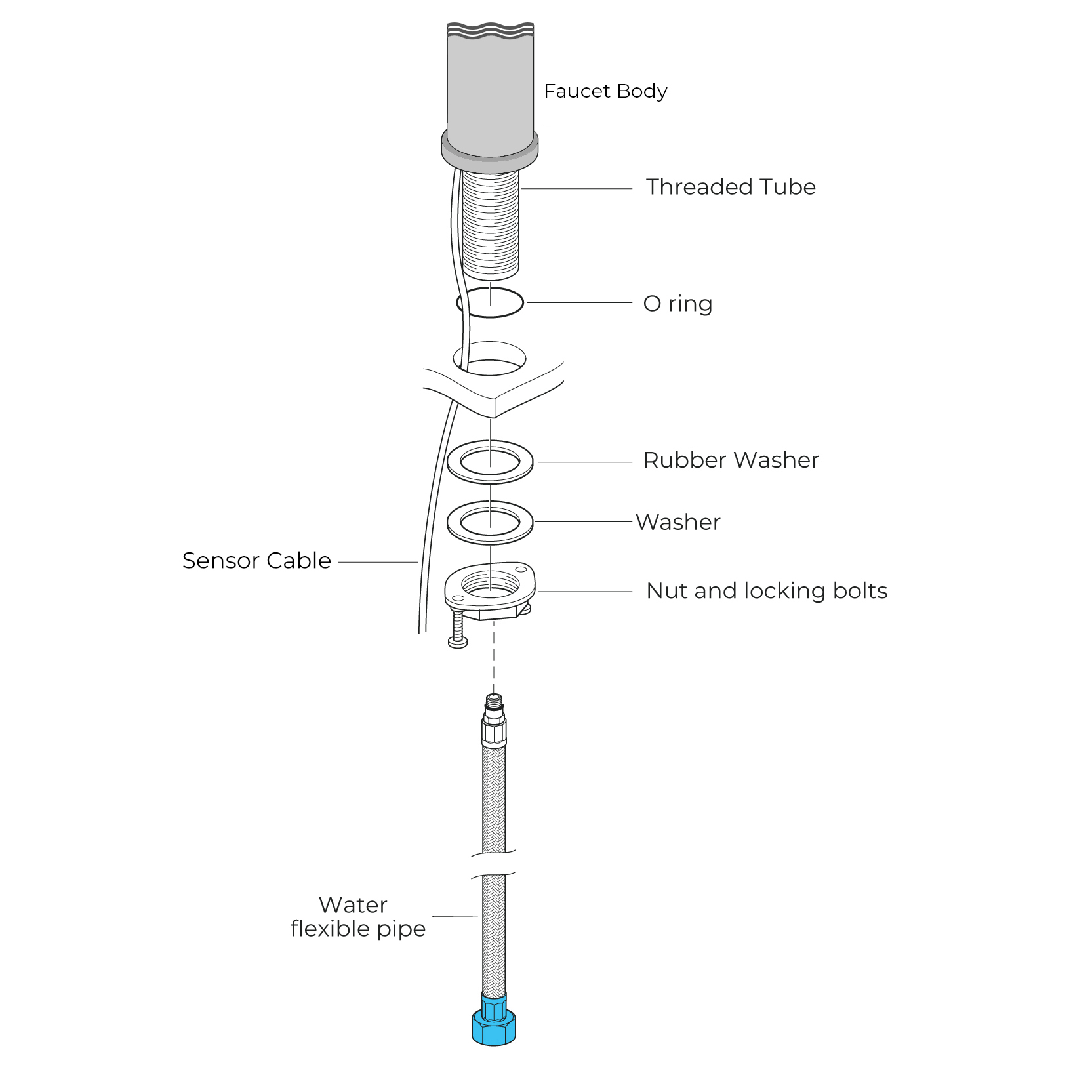 |
| | | | |
|
| Battery (DC 6V) Only Control Box | | | | Step 1: | | Step 2: (Hot & Cold Connection) | 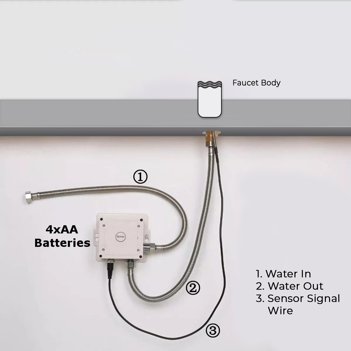
| sensor | 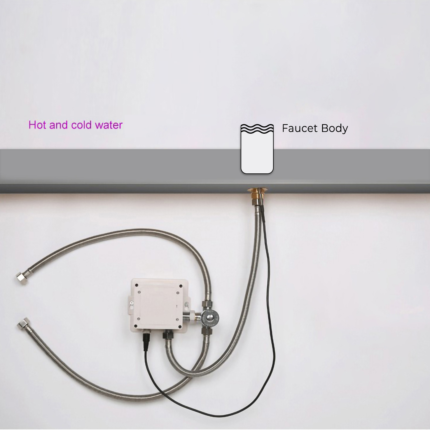 |
| |
| | Battery (DC 6V) & AC 220V Control Box | | | | Step 3: | | Step 4: | 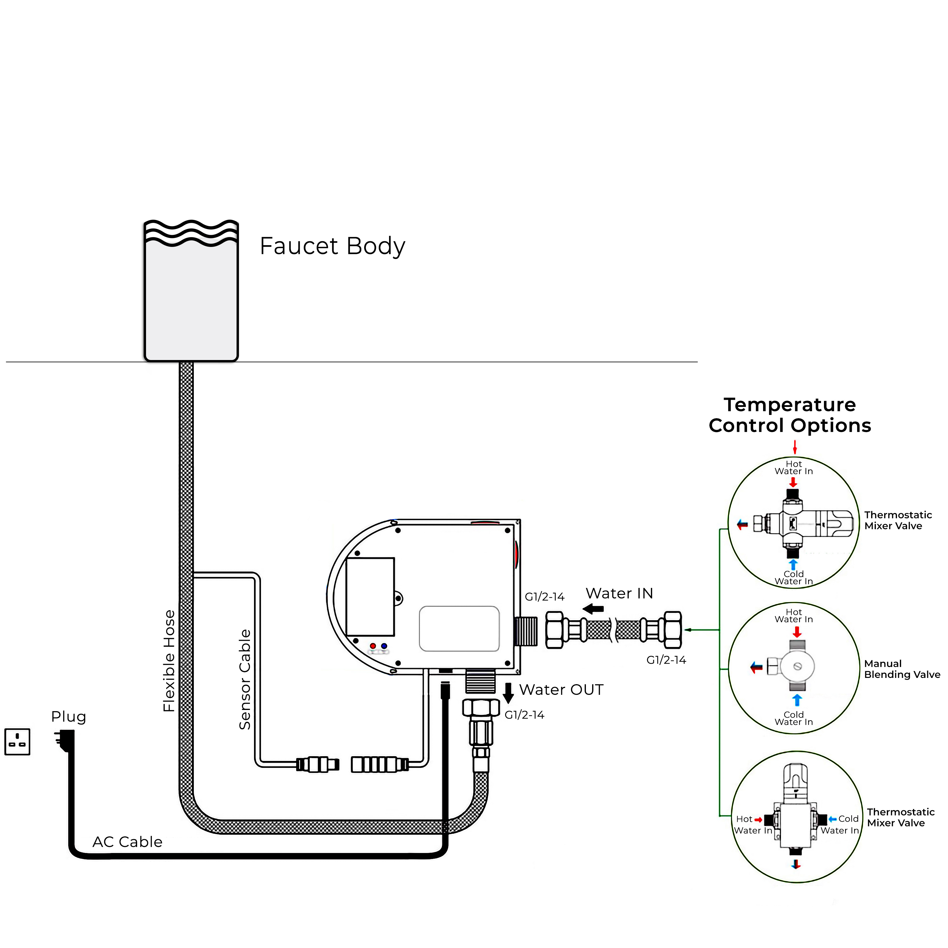 | | 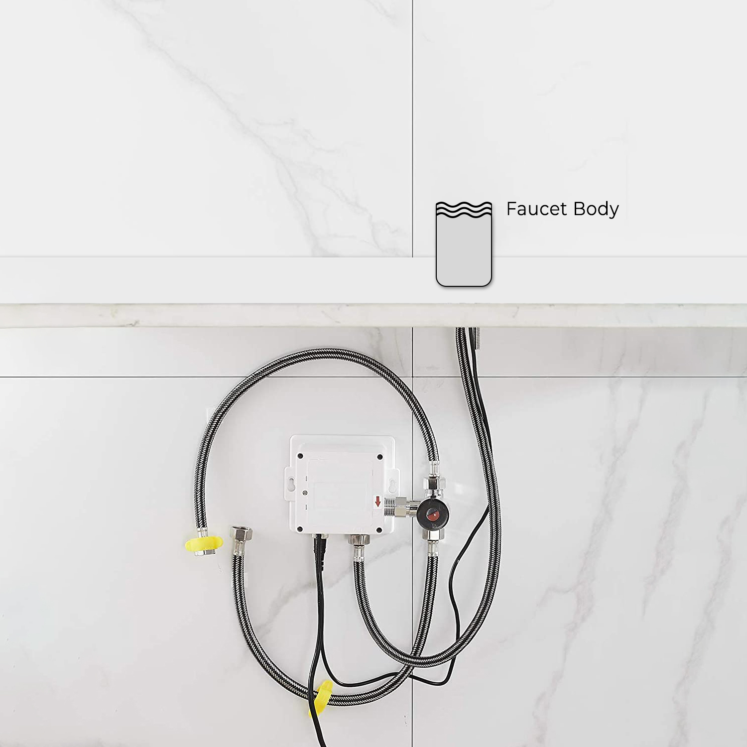 |
| |
| | Step 5: Control Box | | Step 6: Hot & Cold Regulator | 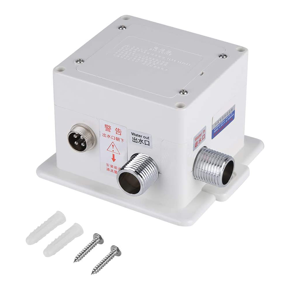 | |  |
| |
| | Step 7: Flush debris from waterpipes | | Step 8: (Correct way for Hose) | 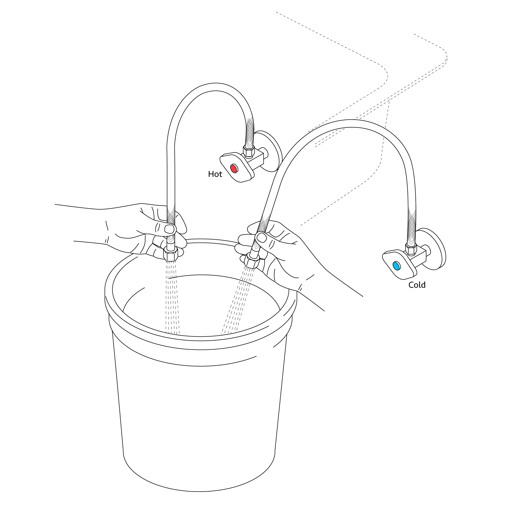 | | 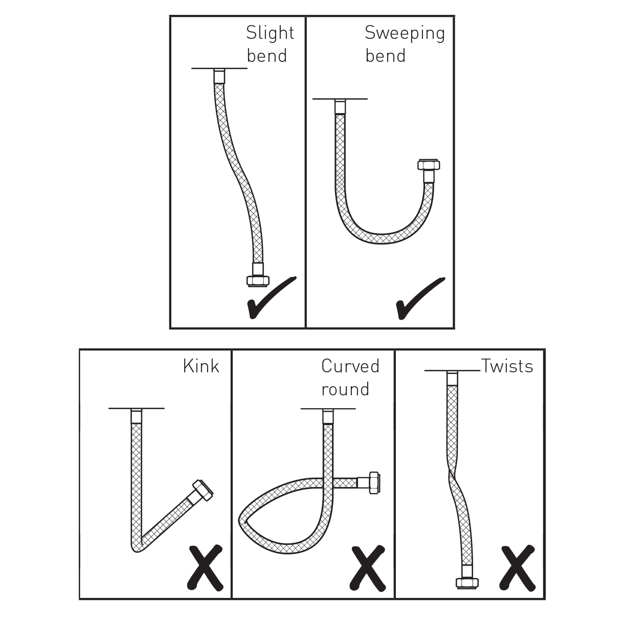 |
| |
|
| | |
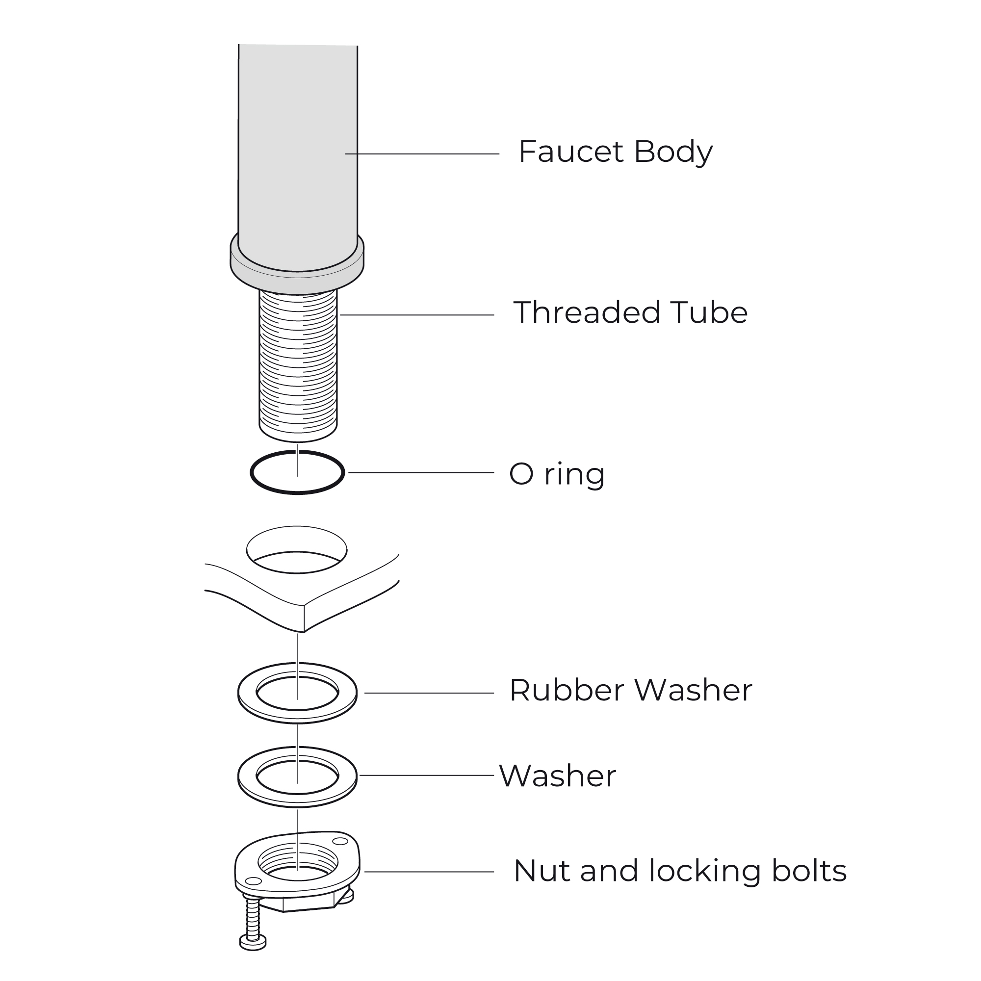
1. Screw the hose into the corresponding screw-hole of the faucet body. Fix the o-ring into the bottom groove of the faucet body.
2. Insert hose, threaded pipe and data cable through the drilled hole of the countertop. Put rubber washer and metal washer onto the threaded pipe, screwing in mounting nut. Adjust the faucet body correctly and tighten the mounting nut with screws.
3. Install the control box to the wall and fix it with screws.
4. Add the rubber washer and screw supply elbow to the control box.
5. Add rubber washers and connect water lines to the hot and cold inlets of the supply elbow. Then connect the hose to the water outlet and insert data cable into the control box and plugin.
6. Make Connections to water supplies. Turn on hot and cold water supplies and flush water lines into a container for one minute. Important: This flushes away any debris that could cause damage to internal parts.
7. Connect waterlines to angle stops. Turn on the angle stops and check for leaks (DO NOT TURN FAUCET ON).
8. Turn the faucet on for 1 minute to flush any debris.
|
|

|
Flexible Connecting Hose
Care must be taken when connecting the flexible connection hose from the power supply box to the spout to ensure it does not bend sharply and kink or twist.
See above for recommended ways to fit the flexible connecting hose.
Important: Failure to follow these guidelines may result in poor performance and damage to the flexible connection hose.
|
|
|
Control Box Installation Instructions
| Step 1: | | Step 2: | 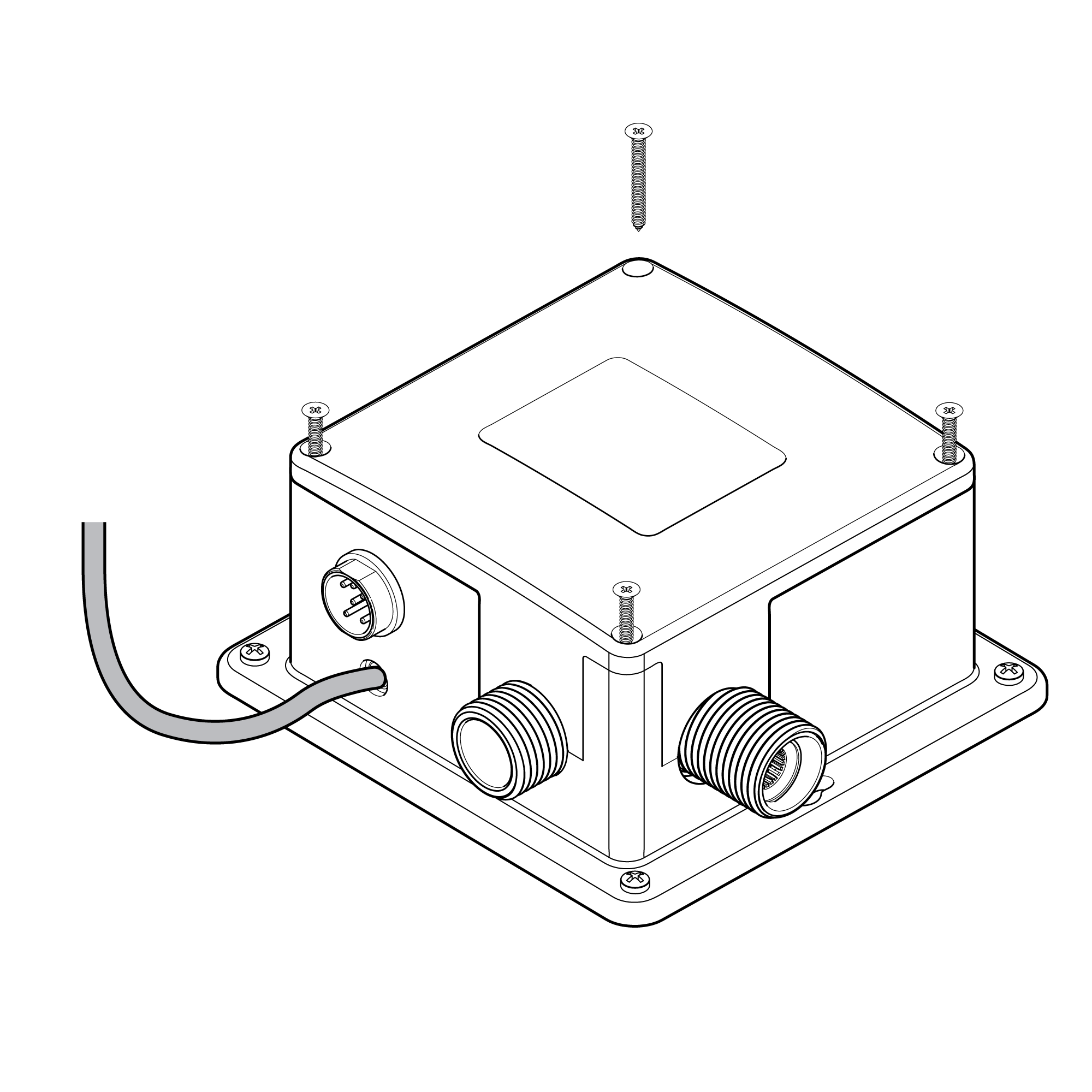 | control box | 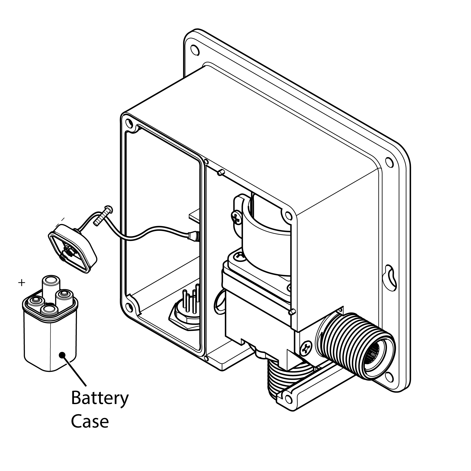 | | | | | Step 3: | | Step 4: |  | | 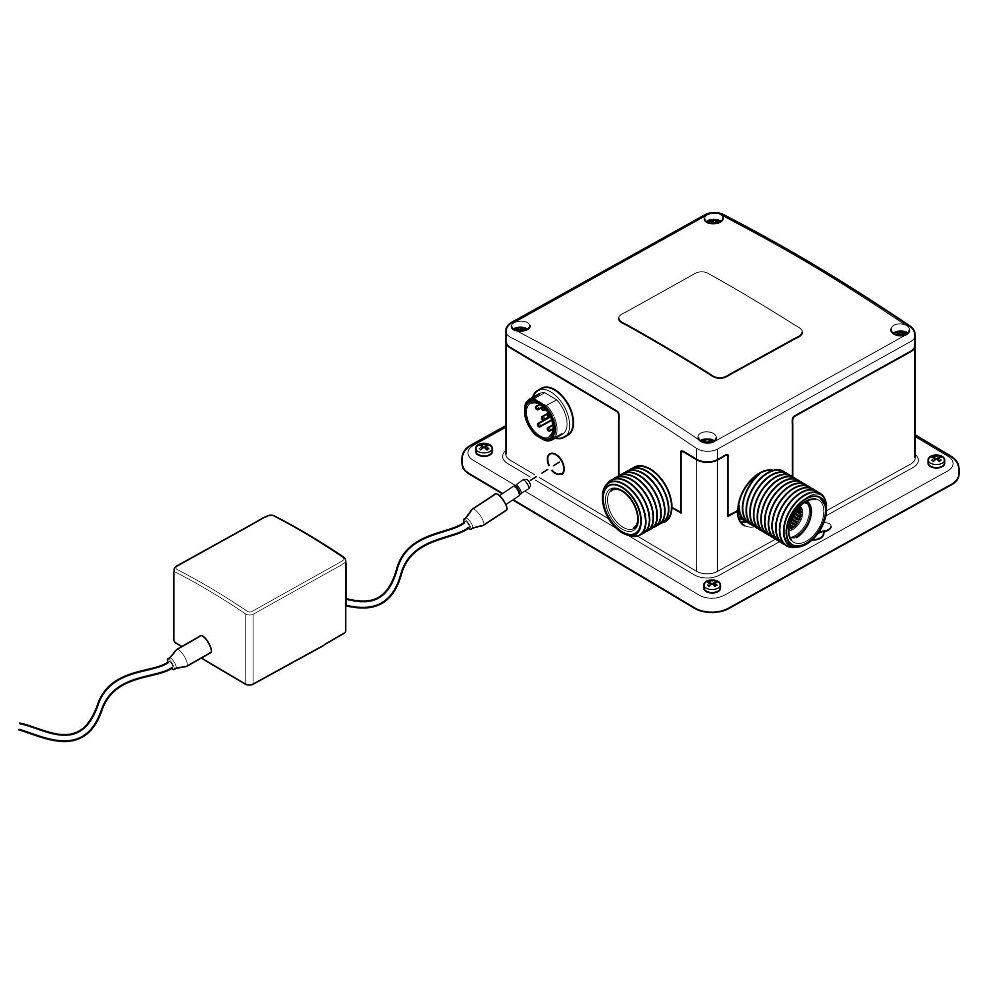 | 5" size
| | | | Step 5: | | Step 6: | 
| |  | | | | | Step 7: Connect to Power Supply | | | 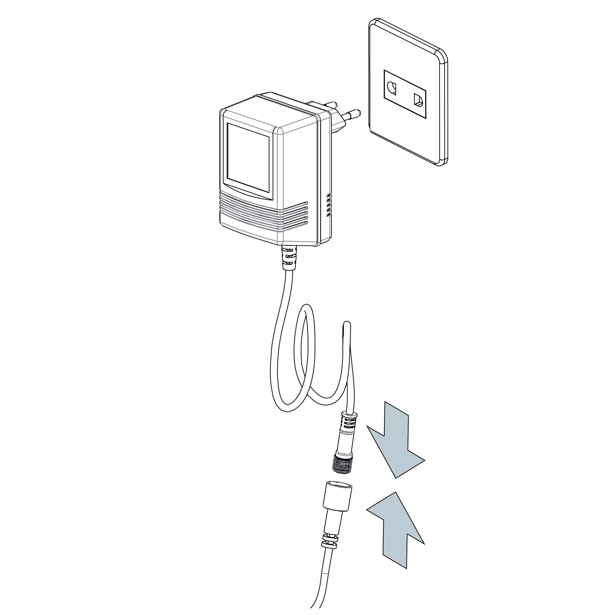 | | | | | |
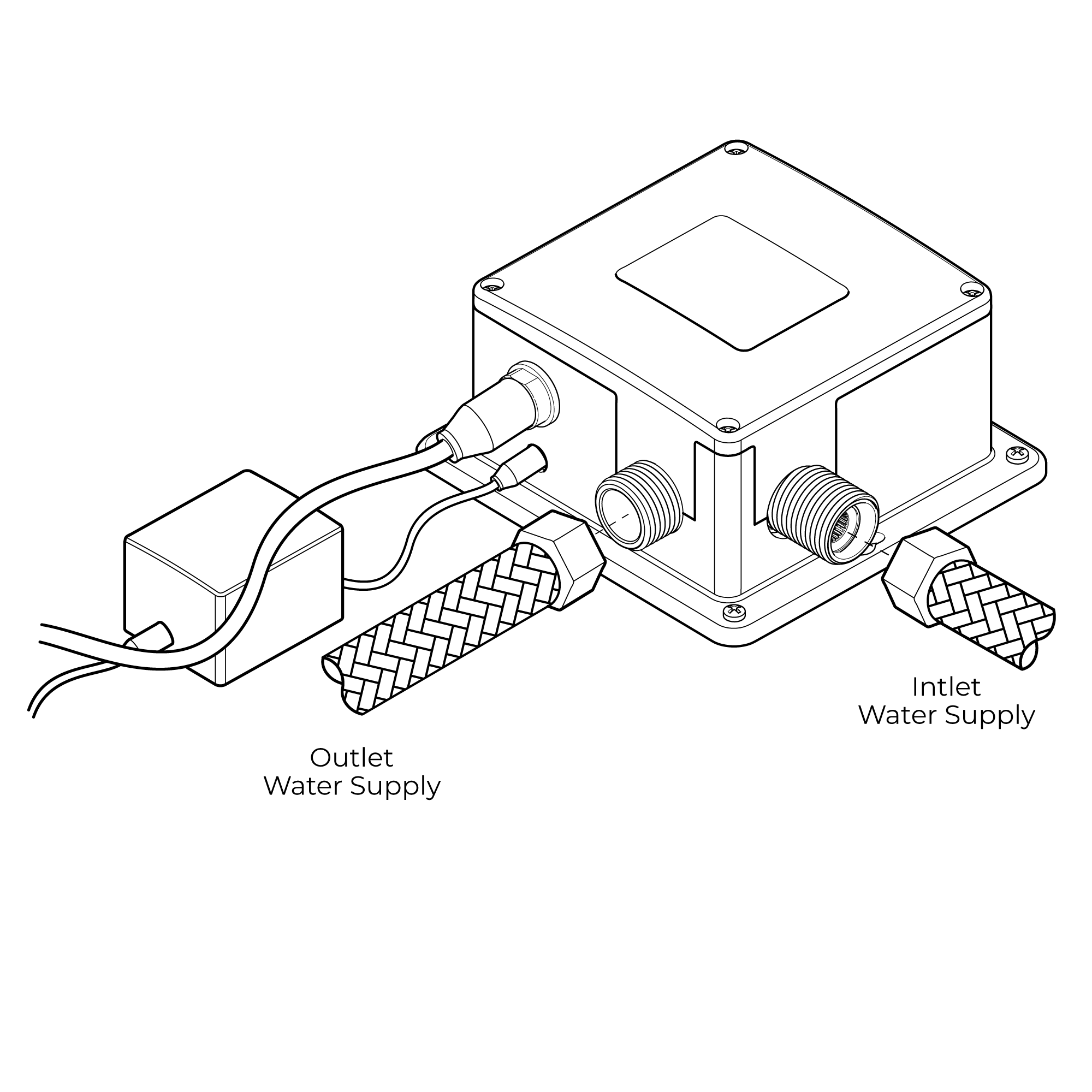
Control Box Installation
1. Remove the four screws from the control box. Remove the control box cover. Remove the battery box from the control box, and gently remove the screw from the battery box cover. Install AA batteries in the orientation shown. Note: Use only alkaline AA batteries. Re-install the battery box cover, matching the alignment arrows together. Set the battery box back into the control box, and re-install the control box cover using the previously removed screws.
2. Choose a location under the sink basin to mount the control box, such that the sensor cable, flexible hose, and incoming water supply all connect to the control box. Under the sink basin, drill a hole minimum 3/4â to fit the sensor cable and flexible hose from the spout. Feed the sensor cable and flexible hose through the hole.
3. Mount the control box to the wall in the orientation shown. Drill four 1/8" (3mm) holes, and push drywall anchors into each hole. Secure the control box to the wall with the drywall screws.
4. Connect the incoming water supply line to the control box, at the connection marked Inlet.
5. Thread on the swivel nut to the hose by hand. Tighten with a wrench.
6. Connect the faucet hose to the control box, at the connection marked Outlet.
7. Slide sensor cable connector over the sensor cable connector on the control box and tighten by hand.
Note: Prior to connecting the sensor cable to the control box, open the water supply stop valve and ensure the sink basin is completely clean and clear of objects, or the sensor will not correctly calibrate. Please wait approximately 60 seconds after connecting the sensor cable for sensor calibration to complete and to begin using the faucet.
| |  | | | |
Inserting Batteries
Your infrared spout is supplied with a backup battery pack (batteries not included). In the event of a power failure the batteries will override the mains power supply to ensure the spout continues to function.
Before fitting the power supply box into position on the wall/floor, batteries (not included) will need to be fitted.
1. Remove Power Supply Box Cover - Remove all four screws in each corner of the power supply box and remove the cover.
2. Remove Battery Box - Remove the battery case from the power supply box and remove the screw in the center of the case.
3. Insert Batteries - Insert 4 x AA batteries (not included) into the battery box ensuring they are inserted the correct way.
4. Replace Battery Box - Replace the battery case cover. Replace and tighten the screw. Insert the battery case back into the power supply box.
5. Replace Power Supply Cover -
|
|
|
|
| |