The Finished Fixture Depends on Work Hidden Behind It
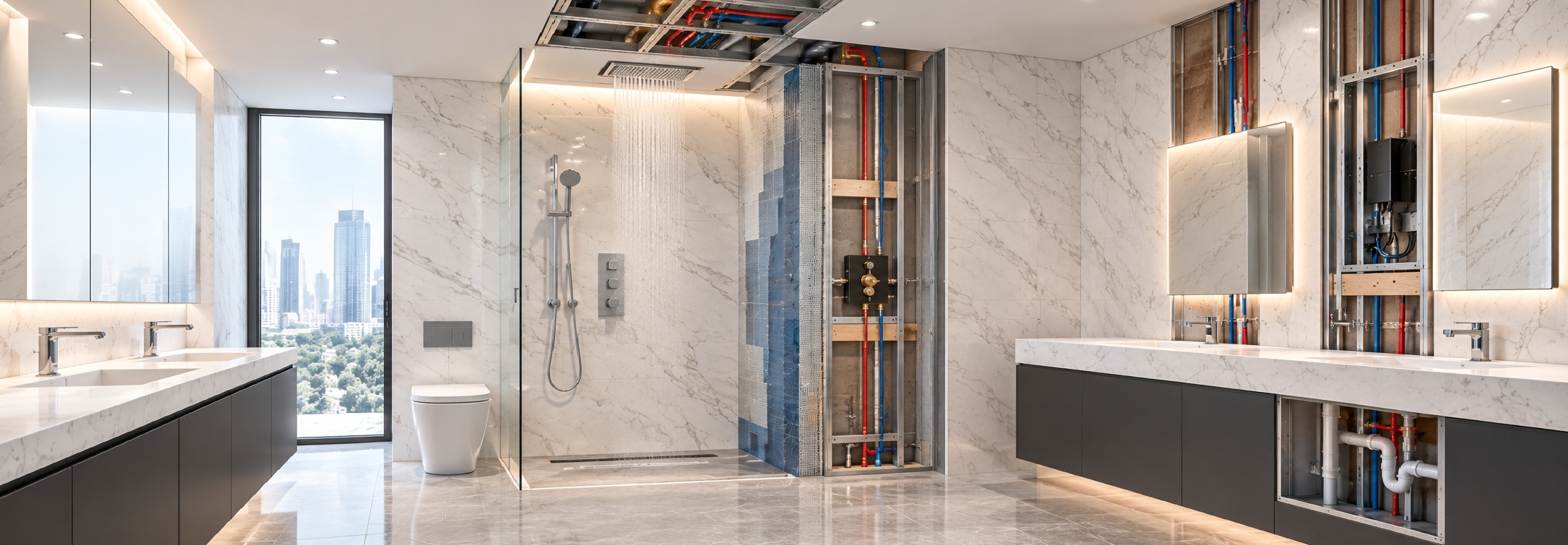
Bathroom fixtures connect architectural finishes with plumbing, electrical systems, structure, waterproofing, millwork and maintenance access. A product can be correctly selected yet fail to fit when the rough-in depth, connection location, ceiling support, counter opening, power supply or service clearance was not coordinated.
This guide organizes the questions that should be resolved before concealed work is closed. Always use current exact-model drawings, installation instructions, approved submittals, engineering calculations, adopted codes and verified field conditions.
Connection sizes, locations, pressure, flow, isolation and hot-water demand
Plumbing engineer and contractor
Drainage
Fixture outlet, trap, waste, overflow, capacity, slope and cleanout access
Plumbing engineer, architect and contractor
Electrical
Voltage, circuits, transformers, batteries, controls, cable routes and access
Electrical engineer and contractor
Structure & Support
Blocking, framing, anchors, ceiling support, tub loads and penetrations
Architect, structural engineer and contractor
Waterproofing
Membranes, penetrations, seals, curbs, slopes and testing sequence
Architect, waterproofing trade and installer
Millwork & Stone
Cutouts, mounting thickness, below-deck clearances and removable access
Interior designer, fabricator and plumbing contractor
Service Access
Valves, filters, solenoids, controllers, transformers and isolation points
Design team, contractor and facility operator
Actual responsibilities must follow the project contracts. The matrix identifies coordination interfaces; it does not reassign professional or trade obligations.
Bathroom fixture rough-in and MEP coordination should resolve mounting geometry, water supply, drainage, electrical access, structural support, clearances, and future service requirements before construction begins, because conflicts between these systems can affect installation, accessibility, and long-term maintenance. Project teams can use the bathroom fixture specification checklist, organize project information through the fixture specification and coordination list, and access the BathSelect Architect & Designer Resource Center when coordinating plumbing, electrical, structural, accessibility, and installation requirements across the fixture package.
Exact-Model Rough-In Package
Control the Information Used in the Field
Required Document
What It Must Show
Verification
Approved Product Data
Exact model, configuration, finish, dimensions and performance
Matches the fixture schedule and submittal disposition
Rough-In Drawing
Centerlines, depths, connections, mounting and concealed components
References the same exact model and revision
Installation Instructions
Sequence, tolerances, supports, utilities, access, testing and limitations
Available to affected trades before installation
Coordinated Detail
Fixture, finish build-up, structure, MEP systems and access in one condition
Conflicts resolved across disciplines
Field Verification
Actual dimensions, surfaces, routing and available conditions
Completed before fabrication or closure
Revision Record
Accepted changes, dates and incorporated drawing updates
Static pressure alone does not establish fixture performance. The plumbing engineer should evaluate available dynamic pressure, elevation, pipe length, fittings, valve losses, simultaneous demand and hot-water capacity at the intended operating condition.
Water-Supply Check
Required Coordination
Connection
Exact size, type, orientation and adapter requirements
Pressure
Available dynamic pressure at the fixture under design demand
Flow
Exact-model rating and combined flow for intended simultaneous functions
Hot Water
Temperature, recovery, distribution and peak-demand capacity
Control
Thermostatic, pressure-balancing, manual, digital or central tempering strategy
Isolation
Accessible shutoff locations for commissioning and service
Flushing
Construction debris control and flushing sequence before connection
Protection
Applicable backflow, pressure, temperature and water-quality provisions
Review model-specific criteria with the
BathSelect Hydraulic Engineering resource. Product information does not replace plumbing engineering calculations.
Drainage Coordination
Connect Fixture Output to the Complete Drainage Design
Shower Demand
Determine the intended simultaneous outlet combinations and coordinate drainage capacity, slope, waterproofing and overflow risk.
Coordinate tub outlet, overflow, waste assembly, access, structural recess and filler location.
Floor Conditions
Resolve drain elevation, floor build-up, membrane, slope, finish thickness and structural penetration before placement.
Cleanouts
Keep required cleanouts accessible after casework, panels, tubs and decorative finishes are installed.
Testing
Coordinate drainage and waterproofing testing before concealment and before finished fixtures are exposed to construction work.
Electrical and Controls
Coordinate Power Before Millwork and Walls Are Complete
Electrical Field
Questions to Resolve
Drawing Impact
Power Architecture
Battery, hardwired, hybrid or other approved arrangement?
Power notes and fixture schedule
Voltage & Circuit
What exact supply, transformer and circuit requirements apply?
Electrical plans and panel schedules
Transformer
Where is it mounted, ventilated, isolated and accessed?
Ceiling, wall or millwork details
Cable Routing
What lengths, pathways, separation and connectors are required?
Coordination plans and elevations
Controller
Where are digital modules or control boxes located?
Access-panel and equipment layouts
Wet Locations
What project and product requirements govern the installation?
Electrical details and specifications
Commissioning
Who energizes, configures, tests and records settings?
Commissioning plan and closeout
Touchless Faucet Coordination
Protect the Detection Zone and Below-Deck Service Space
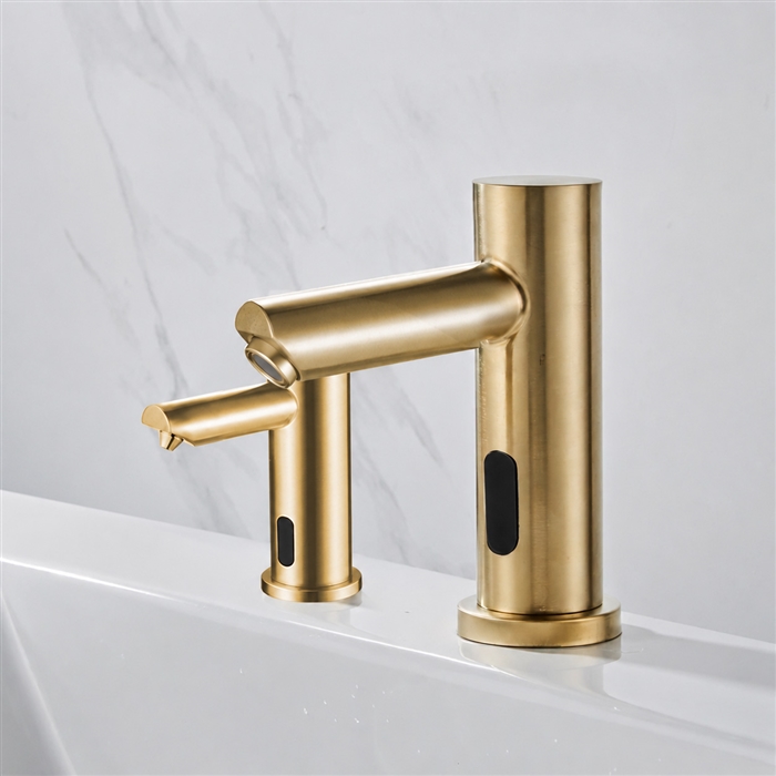
Touchless faucet performance depends on the relationship between faucet, sink, water landing point, reflective surfaces, sensor field, user approach and surrounding accessories. The coordinated detail should show the exact spout location and sink geometry—not only a generic faucet centerline.
Below deck, reserve space for the control box, solenoid, filter, power supply, cables, hoses, mixing device and service access. Check conflicts with the drain, trap, sink supports, soap dispenser, accessible knee clearance and removable millwork panels. Review
Architectural Touchless Faucet Systems.
Shower Wall and Ceiling Coordination
Resolve Depth, Support and Access Before Waterproofing
Condition
Coordination Requirement
Valve Depth
Set against the exact finished-wall plane and permitted installation range
Outlet Layout
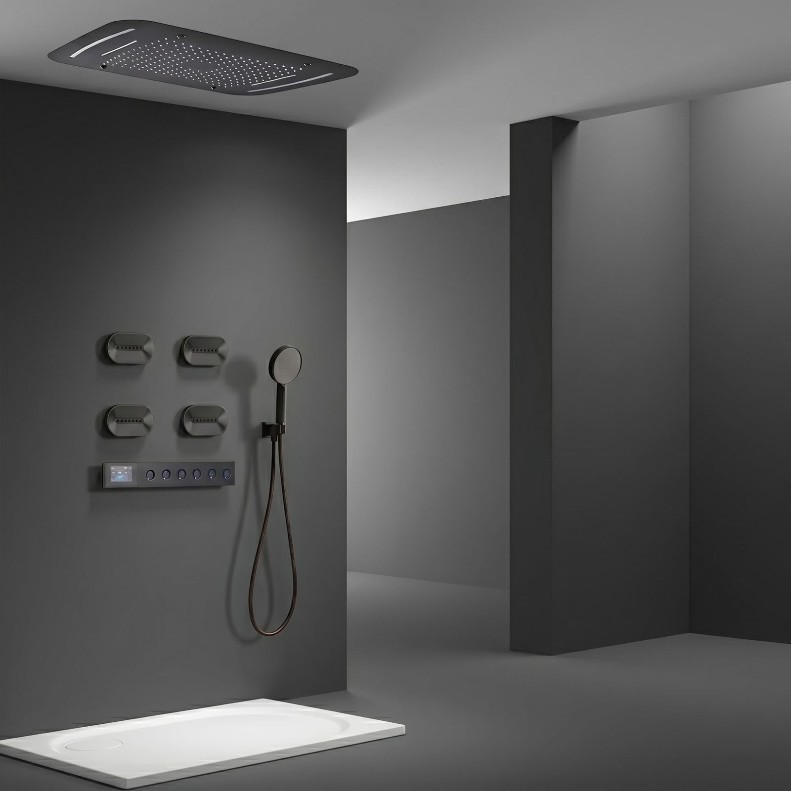
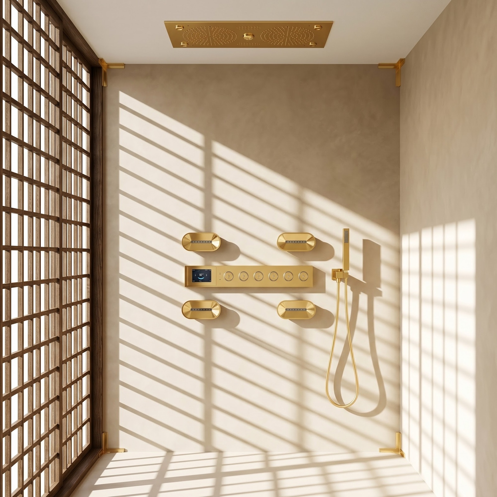
Coordinate body jets, hand shower, controls and head with user position and tile joints
Blocking
Provide support for outlets, slide bars, controls and accessories
Ceiling Head
Coordinate size, weight, support, supply location, finished elevation and access
Waterproofing
Detail every penetration and approved sealing sequence
Digital Module
Locate outside prohibited exposure areas with required power, wiring and service access
Future Service
Provide practical access without destructive removal of primary finishes
Exact number, diameter, spacing, edge distance and mounting thickness
Sink Cutout
Template, reveal, support, adhesive and fabrication tolerances
Water Landing
Spout reach and angle coordinated with bowl geometry
Below-Deck Space
Drain, controls, hoses, soap, supports and access arranged without conflict
Accessible Clearance
Knee and toe space preserved after all components and protection are installed
Removable Access
Panels and doors sized for actual service tasks, not merely visual inspection
Finish Protection
Stone and decorative components protected through commissioning and turnover
An accessible faucet alone does not create an accessible lavatory. Review the complete installed condition and use
Accessible Bathroom Sink Faucets as a product-planning resource.
Service Access
Design Access Around the Actual Maintenance Task
An access panel is useful only when a technician can reach, see, remove and replace the intended component. Identify the access route for cartridges, filters, solenoids, batteries, transformers, controllers, mixing devices, isolation valves, hose connections and tub wastes.
Coordinate panel size, swing, fasteners, finish, nearby equipment and required tools. Avoid locating serviceable components behind permanently bonded stone, inaccessible ceiling features or fixed casework. See
Serviceability Engineering and Lifecycle Engineering.
Preclosure Verification
Inspect Concealed Conditions Before They Disappear
Field Check
Verification
Products
Exact approved rough-ins and concealed components are installed
Locations
Centerlines, elevations, depths, level and orientation are correct
Connections
Sizes, types, alignment, isolation and test status are confirmed
Supports
Blocking, framing, anchors and ceiling attachments are complete
Electrical
Power, transformers, cable routes and control locations are coordinated
Waterproofing
Penetrations, membranes and test sequence match approved details
Access
Service routes remain practical after every finish layer is installed
Record
Photographs, measurements, test results and accepted changes are retained
A drawing for a similar product may use different depths, connections or mounting. Use the exact approved model and revision.
Finish Plane Ignored
Valve depth must account for substrate, waterproofing, adhesive, tile or stone and permitted trim adjustment.
Power Added Late
Touchless and digital systems require coordinated power, controls, routing and access before finishes and millwork close the space.
Insufficient Flow
Multifunction showers require engineering review of dynamic pressure, simultaneous flow, hot-water capacity and drainage.
Blocked Service Access
A nominal access panel may be unusable when stone, framing, equipment or casework prevents component removal.
Unrecorded Changes
Accepted field adjustments should be incorporated into controlled records for commissioning, closeout and future service.
Frequently Asked Questions
Rough-In and MEP Coordination Questions
When should coordination begin?
Begin when fixture types and mounting concepts are established. Confirm exact models before final rough-ins, fabrication and closure.
Who confirms available pressure?
The plumbing engineer should evaluate the project system and dynamic conditions. Product ratings alone do not establish available pressure at the fixture.
Can dimensions be scaled from an image?
No. Use exact-model dimensional and rough-in documents, then verify critical field conditions before installation or fabrication.
Do battery fixtures need electrical review?
They still require coordination of battery type, access, replacement procedure, control components and facility maintenance strategy.
How large should access be?
Size and locate access around the actual inspection, adjustment and component-replacement task, considering tools and surrounding construction.
What should be photographed?
Record concealed valves, supplies, drains, wiring, transformers, supports, waterproofing interfaces, isolation points and access routes before closure.
Coordinate What Is Hidden Before It Becomes Inaccessible.
BathSelect supports project teams with exact-product information, fixture-system planning, installation questions and coordinated project review.
Professional responsibility: BathSelect product information and project support do not replace architectural, plumbing, electrical, structural, waterproofing, accessibility or code review. Requirements vary by project and jurisdiction. Qualified professionals and contractors must verify exact-model data, calculations, field conditions, adopted requirements and installation before concealed work is closed.




 Complete Spa
 Ceiling Shower
 Smart Digital
 Touchless Faucet
 Commercial