The Shower as an Architectural Ceiling Element
What Makes a Ceiling Shower System Architectural?
An architectural ceiling shower is designed as part of the room construction rather than treated as a fixture attached after the ceiling is complete. Its dimensions, mounting method, water connections, lighting, control zones, supports and access requirements must be coordinated before framing and waterproofing are finalized.
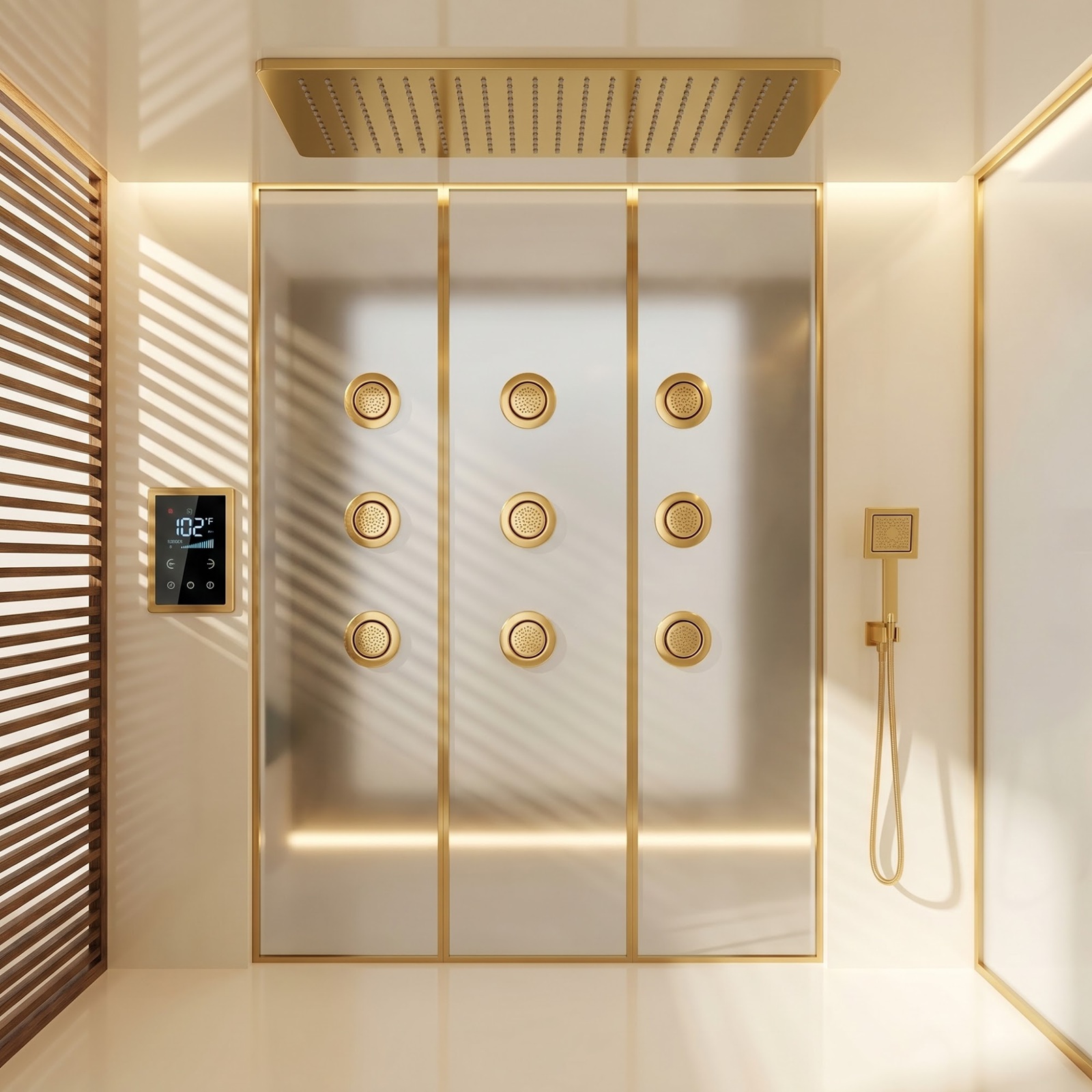
Flush recessed panels can create a visually quiet plane, while surface-mounted ceiling heads express the fixture as a distinct object. Both approaches require accurate rough-in information. Large panels, multiple water functions and integrated lighting increase the need for early coordination among architecture, plumbing, electrical work, waterproofing and interior finishes.
Architectural ceiling shower coordination should begin at the building-interface level, before the overhead fixture is treated as a finish selection. Recessed and surface-mounted assemblies impose different requirements for structural attachment, plenum depth, supply routing, finished ceiling elevation, waterproofed penetrations, electrical and lighting infrastructure, removal clearances, and future service access. Architects, plumbing engineers, and interior teams can resolve those concealed interfaces through the BathSelect bathroom fixture rough-in and MEP coordination guide, integrate the overhead assembly with complete spa shower systems incorporating valves, controls, hand showers, body jets, and coordinated water-delivery zones, and use the complete bathroom fixture-system specification framework to carry structural support, hydraulic demand, waterproofing, electrical coordination, access strategy, and exact-model installation requirements from design development through ceiling closure and commissioning.
Ceiling Shower Configurations
Select the Mounting and Water Functions Together
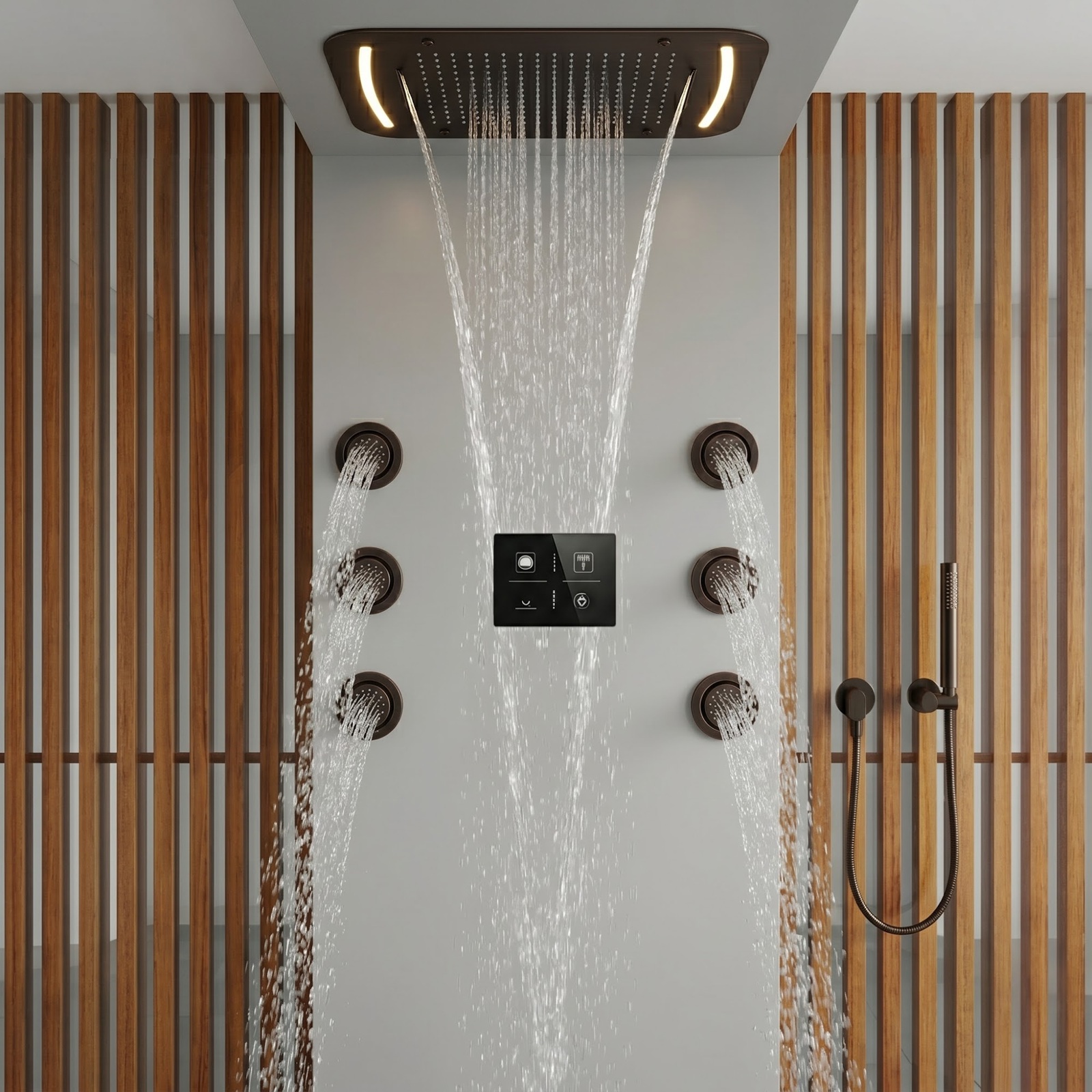
Ceiling systems range from compact round or square rain heads to large rectangular panels combining rainfall, waterfall, mist, water columns or illuminated functions. Configuration affects both the visual ceiling composition and the concealed plumbing required above it.
Ceiling-System Coordination
Four Reviews Before the Ceiling Is Closed.
Ceiling shower performance depends on decisions that become difficult or expensive to change after framing, waterproofing and finishes are complete.
01Mounting
Confirm recessed or surface installation, supports and finished ceiling depth.
02Hydraulics
Verify function flow, simultaneous demand, pressure and valve capacity.
03Penetrations
Coordinate waterproofing, piping, wiring and ceiling transitions.
04Access
Provide a realistic method to inspect connections and replace service parts.
Recessed Versus Surface-Mounted Systems
Choose the Assembly That Matches the Ceiling Strategy
A recessed shower panel aligns closely with the finished ceiling and can produce the most integrated architectural result. It also requires a coordinated rough opening, adequate plenum depth, perimeter detailing, structural support and a defined method for removal or service.
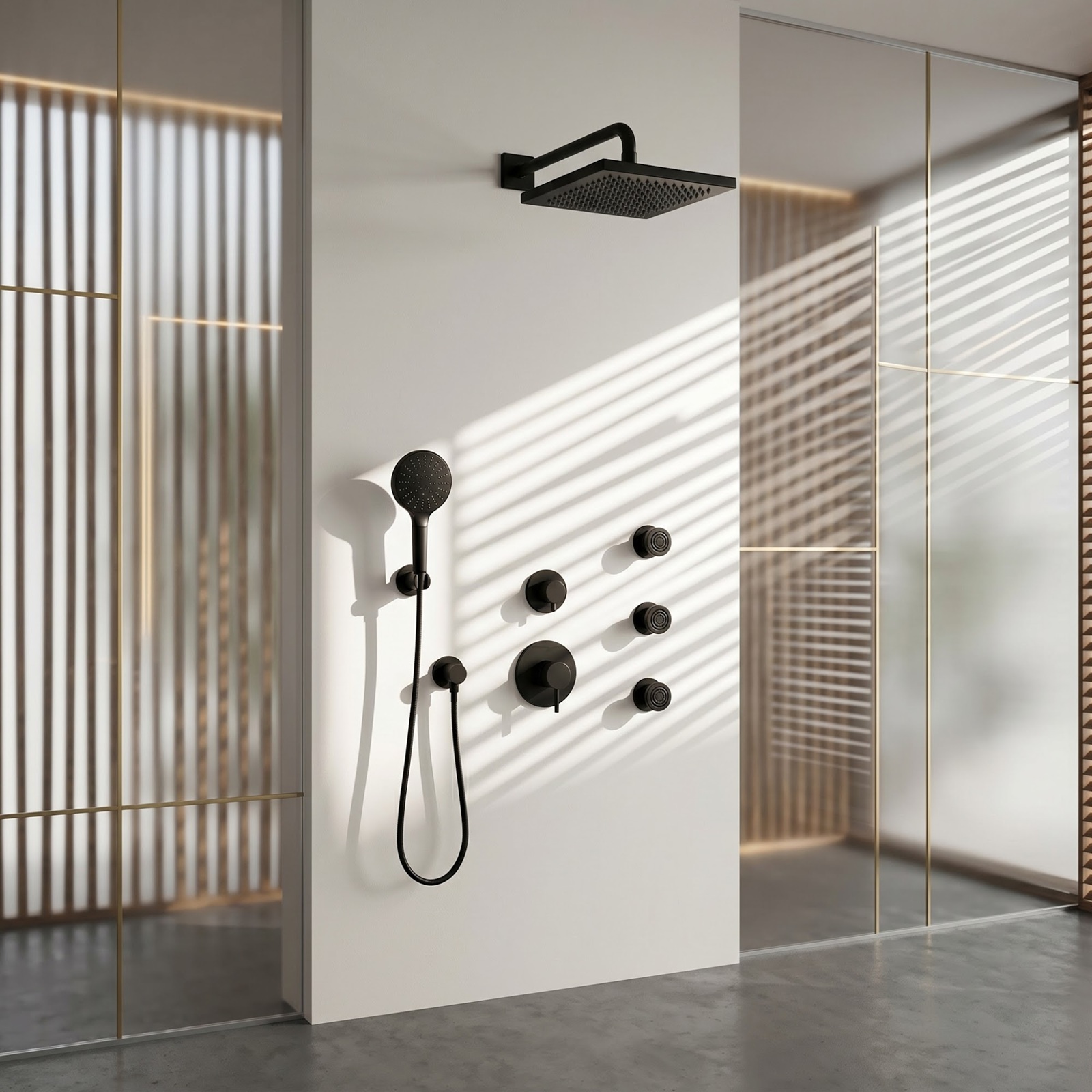
A surface-mounted head or panel generally makes the fixture body and its mounting relationship visible. This may simplify some installation conditions, but it still requires secure support and accurate outlet placement. Short ceiling arms and connection points must be aligned so the fixture sits level and in the intended location.
The selection should be made from model-specific installation information. Terms such as “ceiling mount,” “embedded” and “recessed” are not interchangeable unless the manufacturer’s drawings confirm the same assembly.
Structure, Support and Rough-In Tolerance
Large Ceiling Panels Need More Than a Pipe Connection
The building structure must support the fixture independently of decorative ceiling materials. The responsible design and installation teams should confirm panel weight, attachment points, framing, seismic requirements where applicable and access for tightening or removal.
Rough-in dimensions should be referenced to finished surfaces and coordinated with tile modules, ceiling joints, lighting and enclosure geometry. Even a small offset becomes visually obvious when a large rectangular panel is intended to align with a bench, drain or shower axis.
Where tolerances are limited, a physical coordination review or mock-up can identify conflicts before waterproofing and finish work proceed.
Hydraulic Zoning and Valve Capacity
Calculate Every Function Intended to Operate Together
Multifunction ceiling panels may contain separate rainfall, waterfall, mist or column circuits. The design team must identify which circuits can operate simultaneously, total their rated demand and verify dynamic pressure, supply sizing, mixing-valve capacity, diverter capacity and pressure loss.
Static pressure alone does not establish performance. A large ceiling system may appear adequately supplied until another function opens. Model-specific flow information should be incorporated into the plumbing calculation before valve and piping selections are finalized.
The hot-water system and drain must also be evaluated at maximum permitted combined flow. The ceiling fixture cannot compensate for insufficient heater recovery, undersized piping or inadequate drainage.
Waterproofing and Condensation Control
Coordinate Every Ceiling Penetration as Part of the Wet Area
Ceiling connections, fasteners, access openings and electrical penetrations must be coordinated with the selected waterproofing assembly. Product trim should not be assumed to replace the required water-control detailing behind the finished surface.
Large overhead panels and enclosed showers can also create high local humidity. The project team should review ventilation, ceiling materials and the risk of condensation above or around the assembly. Access panels and service cavities should be detailed for the environmental conditions expected in the room.
Installation responsibilities should be clear: who provides blocking, who seals penetrations, who connects low-voltage components and who verifies the finished assembly before closure.
Lighting, Controls and Electrical Coordination
Identify the Technology Before Electrical Rough-In
Ceiling shower lighting may be water-powered, low-voltage, digitally controlled or integrated with additional features, depending on the model. Each approach has different wiring, transformer, controller and service requirements. The project team must not infer electrical needs from product appearance.
Digital controls should be located where the user can set temperature and select functions without entering an active spray zone. Power supplies, control modules and data connections should remain accessible after construction and be installed in accordance with their listing, instructions and applicable electrical requirements.
The handover package should document normal operation, power interruption behavior, controller replacement and any pairing or commissioning procedure.
Drainage and Splash Containment
Match the Wet Area to the Overhead Coverage Pattern
Architectural ceiling showers can distribute water across a broader area than a conventional wall shower. The shower footprint, enclosure, curb or curbless transition, floor slope and drain placement should be designed around the actual spray envelope.
Waterfall functions and simultaneous outlet operation can create concentrated discharge. Drain capacity should be checked against maximum intended flow with an appropriate project allowance. A visually minimal enclosure should not compromise containment or allow water to reach adjacent dry surfaces.
Serviceability and Lifecycle Planning
Preserve Access Without Weakening the Architecture
Concealment is valuable only when it does not make routine service destructive. The project team should understand how the faceplate, spray modules, lighting, supply connections and internal components can be inspected, cleaned or replaced.
Access may be provided through a removable fixture face, an adjacent dry-side panel, a ceiling access panel or another model-approved method. The selected strategy should be documented in the drawings rather than left for the installer to solve after finishes are complete.
Commissioning should verify level, alignment, function selection, flow, temperature, drainage, lighting and leakage at all concealed connections before the access route is closed.
Water Efficiency and Multiple Showering Devices
Review Combined Flow, Not Only Individual Ratings
Individual WaterSense-labeled showerheads are independently certified for efficiency and performance, but a large ceiling system may include several showering devices or functions. The maximum combined flow must be determined for every permitted operating combination.
The EPA’s
WaterSense showerhead guidance explains the performance and efficiency framework for labeled products. Its technical sheet specifically calls for verifying maximum flow when multiple showering devices operate within one compartment.
Architectural Ceiling Shower Checklist
Information to Establish Before Ceiling Closure
Use these categories to coordinate architecture, plumbing, electrical work, waterproofing and installation.
Assembly
Structure
Hydraulics
Wet Area
Electrical
Closeout




.jpeg)
.jpg)
.jpeg)
.jpeg)
 Recessed
 Surface-Mount
 Rainfall &
 LED
LED.jpeg) Digital
Digital