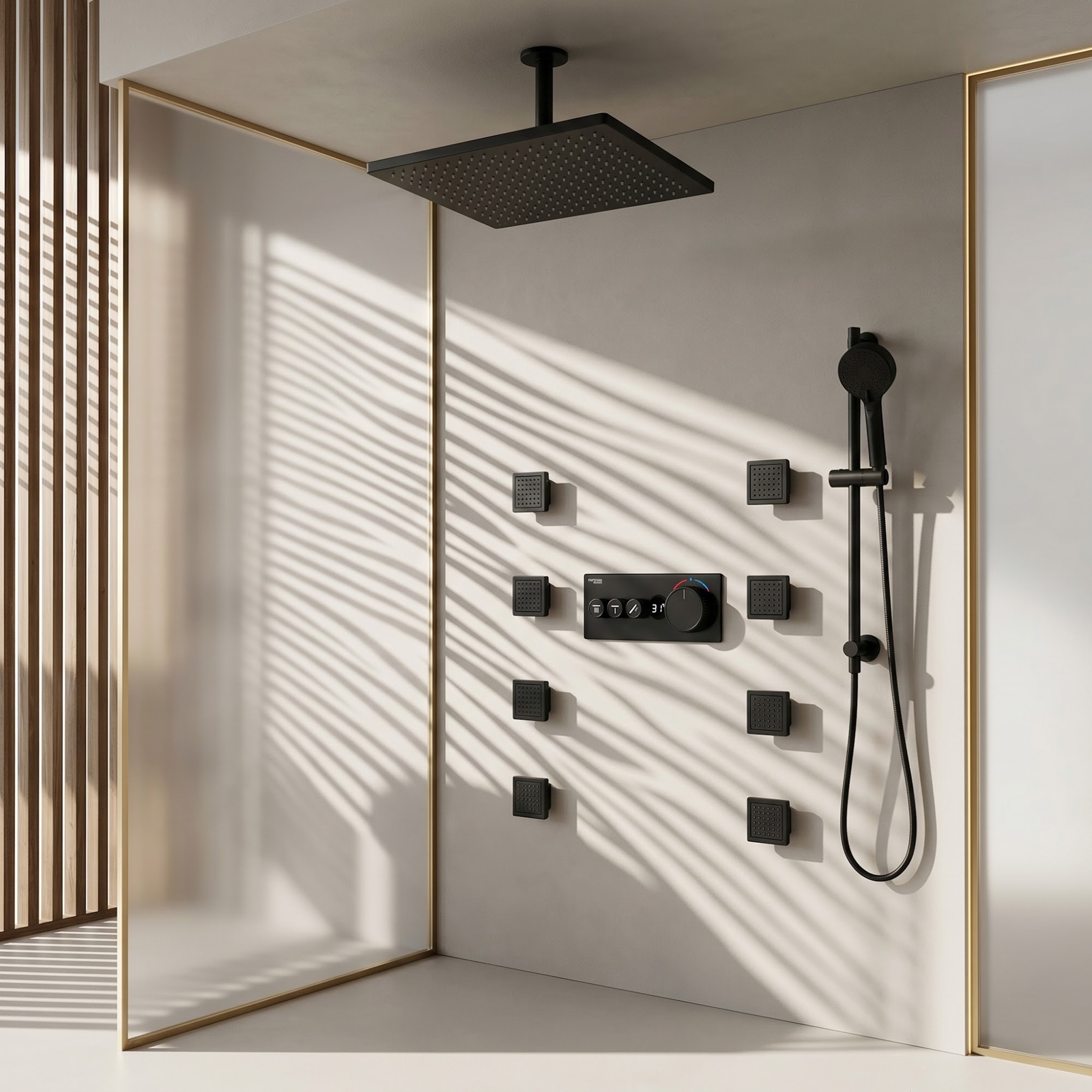
Configuration With a Technical Basis
What Is a Custom-Configured Shower System?
A custom-configured shower system is assembled around the specific needs of a room or project. The process may combine a rainfall head, waterfall outlet, body jets, hand shower, tub spout, thermostatic valve, diverter, digital control or specialty finish into a documented package.
Custom configuration does not automatically mean that every component is custom-manufactured. In many projects, the strongest solution is created by selecting verified compatible products from established families. Any nonstandard fabrication, finish, dimensions or engineering change must be identified and approved separately.
Configuration Paths
Begin With the Room, the User and the Intended Experience
A system can be configured around a compact shower, large wet room, tub-and-shower suite, accessible bathroom, luxury residence or hospitality prototype. Room dimensions, user reach, ceiling construction, outlet position and maintenance access should guide component selection before decorative preferences are finalized.
Configuration Sequence
Four Decisions Before a Product Schedule Is Issued.
A reliable custom configuration follows a controlled sequence from design intent through compatibility and technical verification.
01Design Intent
Define users, room type, experience, mounting and finish direction.
02Functional Package
Select outlets, zones, controls, accessories and operating combinations.
03Technical Verification
Confirm compatibility, flow, valve capacity, utilities and rough-in.
04Approved Schedule
Issue model numbers, finishes, drawings, quantities and revision control.
Outlet and Zone Selection
Specify How the User Will Experience the Water
Every outlet should have a defined purpose. An overhead rain shower provides broad coverage; a waterfall creates concentrated flow; body sprays provide directional coverage; a hand shower adds flexible rinsing and cleaning. More outlets do not automatically create a better system.
The configuration should state which outlets operate independently and which may operate together. That decision controls diverter selection, valve capacity, supply sizing, hot-water demand and drainage. Outlet locations should be coordinated with benches, doors, controls and the user’s standing or seated position.
Compatibility and Component Families
Do Not Assume Similar Appearance Means Technical Compatibility
Showerheads, valves, cartridges, diverters and digital controllers may use different connection sizes, flow ranges and operating logic. Components should be combined only when current technical information confirms compatibility.
The control trim must match the concealed valve. Digital interfaces must be paired with the intended electronic valve and power components. Hand showers, hoses, wall outlets and slide bars should be verified as a functional set. Where components come from different families, each interface should be documented.
A configuration schedule should distinguish required components, optional accessories and items supplied by other trades. This prevents visually complete presentations from becoming incomplete installation packages.
Hydraulic and Hot-Water Verification
Calculate the Maximum Approved Operating Combination
The plumbing calculation should use the total rated demand of all outlets permitted to operate simultaneously. Available dynamic pressure, pipe size, pressure loss, mixing-valve flow and diverter capacity must support that combination.
Custom configurations can increase hot-water demand substantially compared with a single-head shower. Heater output, storage, recovery, recirculation and expected use duration should be reviewed before product approval. The drainage system and wet-area containment must also handle the maximum intended discharge.
The EPA’s guidance for multiple showering devices recommends determining maximum combined flow. Individual outlet ratings alone are not sufficient to describe complete-system demand.
Controls, Temperature Protection and Usability
Match the Interface to the Users and the Outlet Strategy
A thermostatic valve, mechanical diverter or digital controller should be selected according to the number of zones, desired operating combinations and project requirements. The interface should clearly indicate temperature and active functions without requiring unnecessary steps.
Controls should be placed where they can be reached before the user enters the spray. Accessible projects require additional review of reach range, operable parts, hand-shower location and the complete shower-compartment layout.
Temperature protection and valve certification must be verified for the selected model and jurisdiction. A product description should never be used as a substitute for current technical data and the responsible professional’s code review.
Rough-In, Waterproofing and Service Access
Document Concealed Work Before Construction Begins
Custom configurations create multiple concealed connections and penetrations. Drawings should locate valves, outlets, body jets, controls, power components and access points from finished surfaces. Ceiling and wall assemblies must provide appropriate supports and waterproofing transitions.
Serviceable components should remain accessible without destructive removal of tile or stone. The design should identify how cartridges, solenoids, electronic modules, transformers, filters and supply connections can be reached after project completion.
When nonstandard dimensions or custom fabrication are proposed, approval drawings should govern production and rough-in. Verbal descriptions are not adequate for dimensional coordination.
Finish and Bathroom-Wide Coordination
Create One Design Language Across the Fixture Package
Custom configuration allows the shower system to align with faucets, tub fillers, drains and bathroom accessories. Finish coordination should be established by product family and approved sample where visual consistency is critical.
Finish names are not universal color standards. Brushed gold, bronze, nickel and black can vary among manufacturers, materials and production processes. A project that combines unrelated products should anticipate those differences rather than assume an exact match.
BathSelect’s broad range of shower functions and finishes provides a strong basis for coordinated packages, while the final schedule records the exact model and finish for each component.
Submittals, Mock-Ups and Revision Control
Protect the Approved Configuration From Uncontrolled Changes
The submittal should include a component schedule, installation drawings, flow information, valve data, finish selections, electrical requirements where applicable and an explicit list of operating zones. Every item should be traceable to a model number.
Large or complex systems benefit from a mock-up that verifies control sequence, outlet position, splash containment and user reach. If an alternate is proposed, the comparison should address the entire configuration—not only the visible showerhead.
Revisions must be coordinated across connected components. Changing a showerhead, adding body jets or substituting a valve can alter flow, pressure, hot-water and rough-in requirements. The approved schedule should carry a revision date and responsible review.
Water Efficiency and Configuration Choices
Control Combined Demand Through Deliberate Zoning
Water-efficient outlets can reduce individual flow, but system use is determined by how many outlets operate together and for how long. Zoning can preserve a varied shower experience while limiting unnecessary simultaneous demand.
The EPA’s
WaterSense showerhead guidance describes independently certified efficiency and performance for eligible products. Its technical sheet recommends verifying maximum flow when multiple devices can operate within one shower compartment.
Custom Shower Configuration Checklist
Information Required for a Coordinated System
Use these categories to move from design intent to an approved, installable fixture package.
Project
Outlets
Controls
Engineering
Installation
Approval





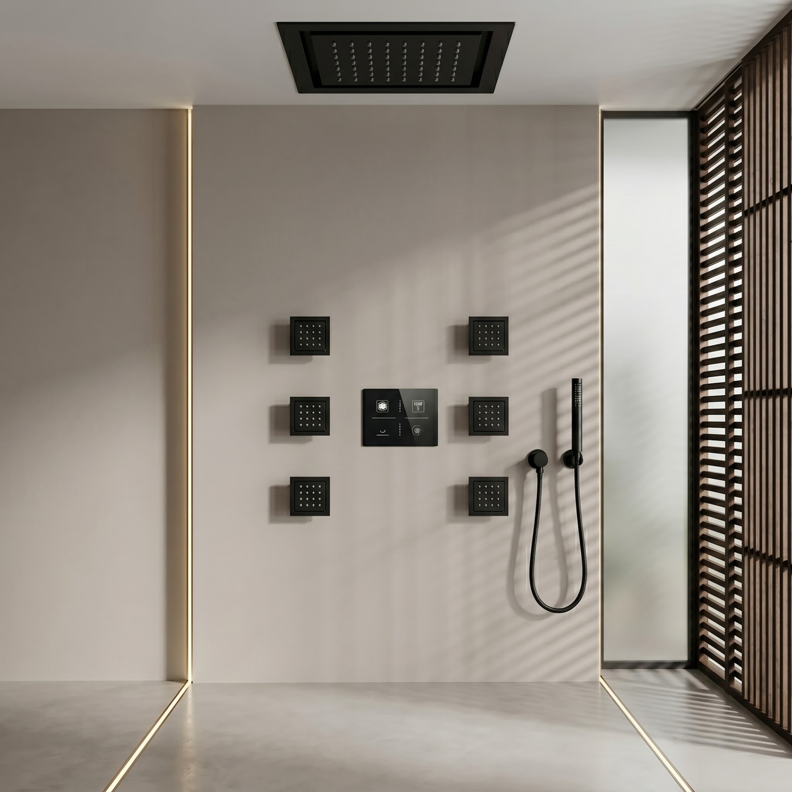
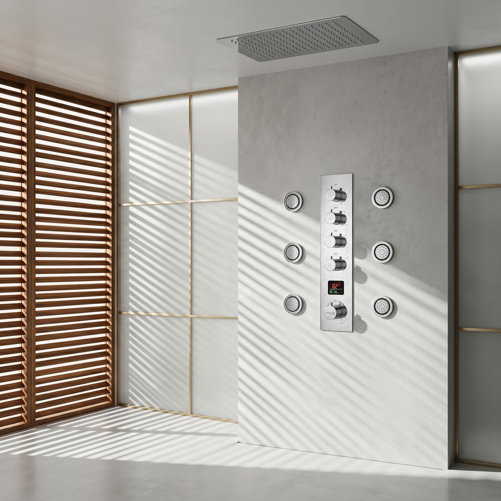

 Multi-Jet
 Ceiling-Mount
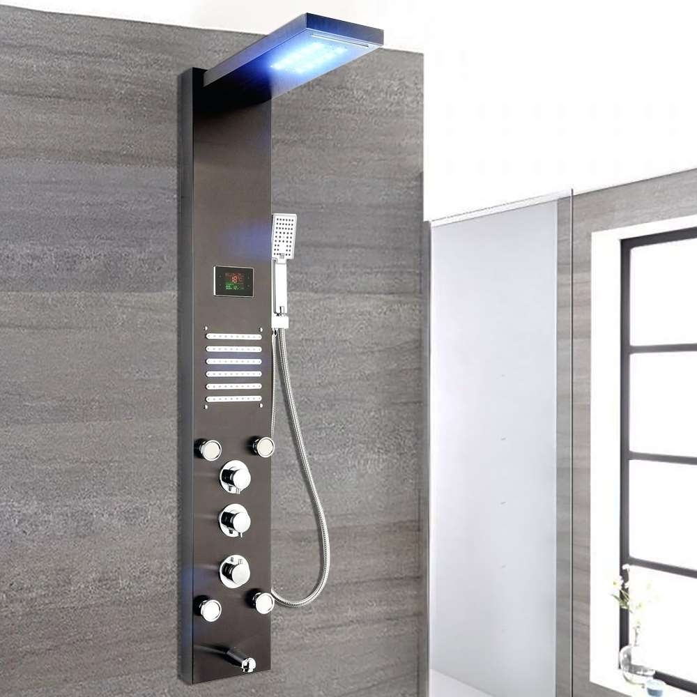 LED
LED