Infrastructure Lifecycle Durability Engineering for Solid Brass Sensor Faucets in Airport Environments
Airport restrooms place unusual demand on faucet systems: high activation frequency, continuous public use, frequent cleaning, limited maintenance windows, and strict accessibility expectations. This article explains how solid brass commercial sensor faucets are evaluated for lifecycle durability, reliability, serviceability, and specification readiness.
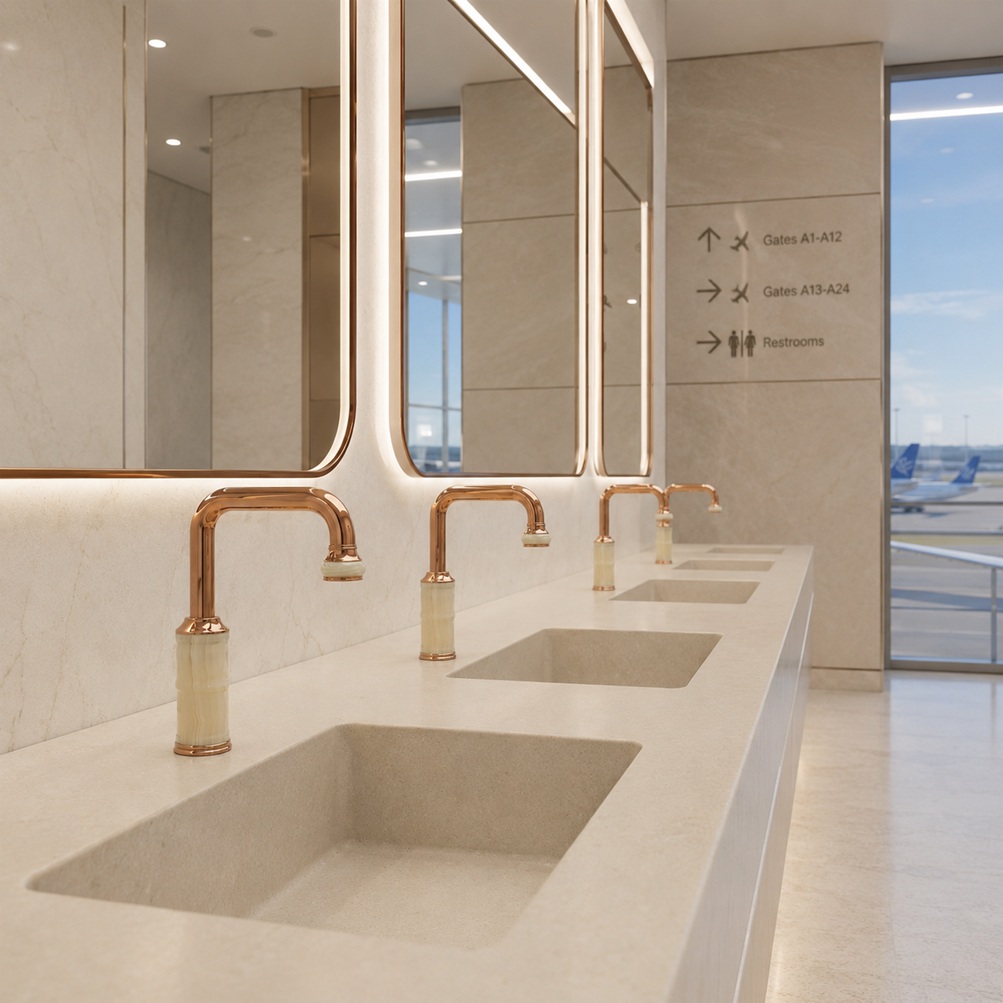
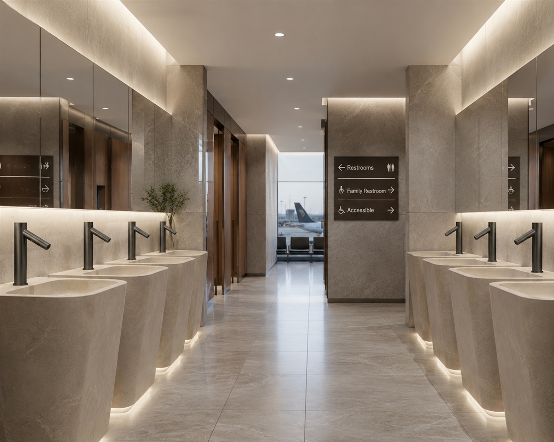
Airport restroom environments require durable faucet bodies, stable sensor operation, accessible lavatory planning, and efficient service access.Cycle testing setup for actuation count, pressure variation, leakage review, and solenoid response stability.Solid brass body architecture supports deck stability, valve alignment, and long-term structural reliability.
Why lifecycle durability matters
Commercial sensor faucets are not decorative accessories in high-traffic facilities; they are operational infrastructure. In airports, a single faucet can be activated hundreds or thousands of times per day. Each cycle exposes the system to hydraulic pressure changes, solenoid actuation, seal movement, sensor triggering, cleaning chemistry, and user interaction.
A reliable faucet platform must therefore be assessed as a complete system: body material, valve architecture, sensor electronics, mounting stability, finish durability, accessibility, and service continuity. The goal is not only to survive initial installation, but to maintain consistent operation across years of public use.
These official and standards-body references support the article’s compliance context. Product-specific certification should always be confirmed on the final submittal package for the selected model.
Durability analysis begins with the expected operating profile. Airport faucet systems are exposed to short, repeated activation events rather than long continuous flow. The resulting duty cycle stresses the solenoid valve, seal interfaces, mounting hardware, aerator, sensor window, and faucet body.
For specification review, lifecycle testing should document activation interval, water pressure range, cycle count, leakage results, sensor response stability, and post-test component inspection. A meaningful test program evaluates the faucet as an installed system rather than a loose component.
Cycle-test criteria to request
Activation interval and total completed cycles
Pressure range used during testing
Leakage and seal-integrity observations
Solenoid response consistency before and after testing
Mounting stability and sensor window condition
Cycle testing rig for activation frequency, hydraulic pressure, solenoid actuation, and leak inspection.Lifecycle curve showing accumulated cycles, fatigue behavior, and service-life planning thresholds.High-frequency public use is the operating condition that drives lifecycle durability requirements.
Reliability engineering, MTBF, and Weibull review
Reliability claims should be evaluated in context. Mean Time Between Failures, Mean Cycles Between Failure, and Weibull modeling are useful only when the assumptions are transparent. Facility teams should ask how failure was defined, how many samples were tested, what water pressure was used, and whether the test included sensor response, solenoid actuation, leakage, and finish condition.
MCBFMean cycles between failure used for fixture lifecycle planning
MTBFTime-based reliability estimate tied to expected annual activations
WeibullDistribution model used to assess wear-out behavior and reliability trends
Specification note
Do not treat reliability values as universal unless the selected faucet model, sample size, test duty cycle, pressure range, and maintenance assumptions are documented. Product-specific submittals should be reviewed before final project approval.
Weibull curve for reliability review and long-term wear-out behavior.MTBF dashboard for converting cycle-life assumptions into service planning.Failure-mode mapping helps identify where reliability controls should be reviewed.
Material science: why solid brass is specified
Material selection has a direct effect on fatigue resistance, corrosion resistance, dimensional stability, and long-term serviceability. Solid brass faucet bodies are commonly specified in demanding public environments because they provide structural strength at threaded connections, mounting interfaces, valve cavities, and spout bases.
Specification factor
Solid brass body
Lower-grade alternatives
Mounting stability
Supports rigid deck attachment and long-term alignment.
May be more vulnerable to loosening, distortion, or cracking.
Thread and valve integrity
Maintains stronger interfaces for supply connections and internal valve assemblies.
Threads and valve seats may show accelerated wear under repeated service.
Cleaning exposure
Can be paired with durable finishes for institutional cleaning routines.
More dependent on coating quality and may be less tolerant of harsh environments.
Service life
Well suited for high-cycle commercial restroom installations.
Better suited for low-traffic or short-cycle applications.
Cross-section view of solid brass faucet body, deck mount, and internal valve geometry.Material comparison for body strength, fatigue resistance, and service durability.Stress analysis reference for mounting interfaces and spout-base loading.
Environmental durability and cleaning exposure
Airport and institutional restrooms are cleaned frequently. Faucets must tolerate moisture, humidity, disinfectants, hand soaps, mineral deposits, and repeated wipe-down procedures. Environmental validation should consider finish integrity, corrosion resistance, sensor window clarity, aerator function, and seal performance.
Environmental checks
Salt spray or corrosion screening where applicable
Humidity exposure and temperature cycling
Cleaning chemical compatibility review
Finish adhesion, discoloration, and surface degradation review
Maintenance checks
Aerator clogging and replacement procedure
Sensor window cleaning and false-trigger prevention
Solenoid debris sensitivity and filter access
Battery or low-voltage power maintenance, if applicable
Salt spray and corrosion screening supports finish and material review.Chemical exposure checks help evaluate finish, seals, and sensor-window durability.Humidity and temperature cycling evaluates electronics, seals, and body stability.
Serviceability and maintenance ecosystem
A faucet that cannot be serviced quickly becomes a facility liability. Airports need modular components, predictable replacement parts, and maintenance procedures that minimize restroom downtime. The most serviceable platforms allow access to solenoid valves, control modules, aerators, batteries or power supplies, and sensor components without removing the entire faucet body.
Replaceable modules
Sensor, solenoid, aerator, control module, power supply, seals, and diaphragms should be separately replaceable where possible.
Fast maintenance
Clear access points, standardized fittings, and documented procedures reduce service time and help maintenance teams support large fixture counts.
Parts continuity
Long-term parts availability is essential for facilities that expect faucets to remain in service across multiple budget cycles.
Exploded assembly identifies field-replaceable modules and hydraulic interfaces.Below-deck service access reduces downtime during maintenance.Replacement parts continuity supports long-term facility operations.
Specification compliance and accessibility planning
Commercial restroom faucet selection should be coordinated with plumbing supply fitting standards, potable water contact requirements, corrosion test references, and accessibility requirements. The official standards listed above provide the compliance framework, while the selected product submittal confirms which requirements are met by a specific model.
Defines accessibility expectations for buildings and facilities, including restrooms and lavatory access.
Accessible lavatory planning includes reach range, knee clearance, and sensor activation zone.Compliance map connecting standards references to faucet submittal documentation.Submittal packages should include specs, installation instructions, maintenance guidance, and compliance documentation.
Recommended infrastructure applications
Solid brass touchless sensor faucets are best suited to projects where durability, hygiene, water-use control, and service continuity are important. The strongest applications are high-traffic or high-accountability environments where fixture failure can affect operations, reputation, or maintenance cost.
Airport terminals and transportation hubs
Hospitals, clinics, and healthcare support spaces
Government and institutional buildings
Stadiums, convention centers, and public venues
Commercial office towers and hospitality restrooms
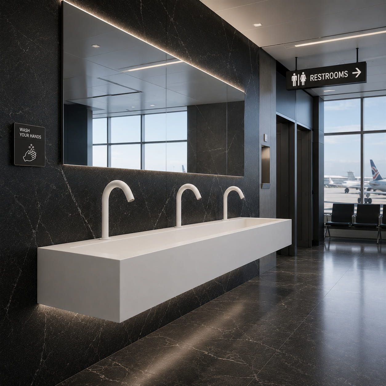
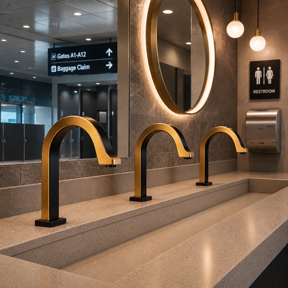
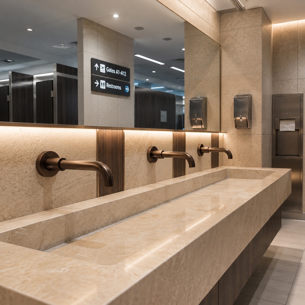
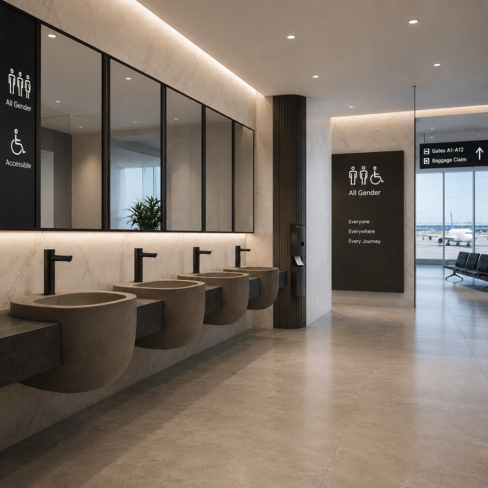
High-traffic applications require lifecycle durability and dependable service access.Healthcare environments benefit from low-touch operation and reliable handwashing access.Transit hubs and public venues need fixtures designed for repeated public use.
Featured BathSelect product references
Commercial Solid Brass Sensor Faucet Platform
Core collection for infrastructure-grade faucet specification.
Why specify solid brass sensor faucets for airports?
Solid brass bodies provide the mechanical stability and service durability needed in high-traffic public restrooms. They are especially useful at the mounting deck, spout base, and valve interface where repeated use and maintenance create stress.
What should a lifecycle test report include?
Request cycle count, pressure range, activation interval, leakage results, component inspection notes, sensor response data, and test sample details.
How should reliability claims be reviewed?
MTBF, MCBF, and Weibull values should be reviewed with their assumptions. Ask how failure was defined and what water pressure, duty cycle, and maintenance conditions were used.
Which documents belong in a submittal package?
A complete package should include product specification sheets, installation instructions, maintenance guidance, finish data, water connection details, accessibility notes, and applicable certification documentation.
Engineering Evidence Model for Commercial Sensor Faucet Lifecycle Planning
This engineering model converts a 1.5 million activation-cycle validation target into practical planning data for airport restroom projects. It helps architects, facility managers, and specification teams understand how daily traffic affects projected service intervals, inspection timing, and component-level reliability review.
Lifecycle charts, MTBF conversion, and failure-risk analysis
The following engineering model supports high-traffic commercial restroom planning by translating activation-cycle durability into calendar-based maintenance and specification review data.
Engineering disclosure: These charts are a planning model, not a replacement for product-specific laboratory certification. Final values should be updated with actual model-level test data, sample size, water pressure range, failure definition, and completed test-cycle records from the selected faucet submittal package.
Annual activations = daily activations × 365Years to 1.5M cycles = 1,500,000 ÷ annual activationsMTBF calendar hours = MCBF ÷ average activations per hour
Airport duty-cycle conversion
This chart shows how quickly a commercial sensor faucet can reach 1.5 million activations under different airport restroom traffic profiles.
Interpretation: at 1,000 activations per day, a faucet reaches 1.5M cycles in roughly 4.1 years. At 500 activations per day, the same target represents about 8.2 years of use.
Preventive maintenance trigger curve
This chart converts cycle accumulation into inspection timing. For high-accountability facilities, the first detailed inspection should occur before the target life is fully consumed.
Interpretation: for a 1,000/day faucet location, a 70% service review occurs at about 1.05M cycles, or roughly 2.9 years. That is a better inspection point than waiting for full cycle consumption.
MTBF / MCBF conversion table for airport specification planning
Mean Cycles Between Failure is more useful than MTBF for sensor faucets because faucet stress is driven by activation count. MTBF becomes useful only after converting the cycle model into real airport traffic assumptions.
Daily activation scenario
Annual activations
Years to 1.5M cycles
Equivalent MTBF calendar hours
Suggested detailed inspection point
Daily activation scenario: 250 activations/day
Annual activations: 91,250 cycles/year
Years to 1.5M cycles: 16.4 years
Equivalent MTBF calendar hours: 144,000 hours
Suggested detailed inspection point: 11.5 years / 1.05M cycles
Daily activation scenario: 500 activations/day
Annual activations: 182,500 cycles/year
Years to 1.5M cycles: 8.2 years
Equivalent MTBF calendar hours: 72,000 hours
Suggested detailed inspection point: 5.8 years / 1.05M cycles
Daily activation scenario: 750 activations/day
Annual activations: 273,750 cycles/year
Years to 1.5M cycles: 5.5 years
Equivalent MTBF calendar hours: 48,000 hours
Suggested detailed inspection point: 3.8 years / 1.05M cycles
Daily activation scenario: 1,000 activations/day
Annual activations: 365,000 cycles/year
Years to 1.5M cycles: 4.1 years
Equivalent MTBF calendar hours: 36,000 hours
Suggested detailed inspection point: 2.9 years / 1.05M cycles
Daily activation scenario: 1,500 activations/day
Annual activations: 547,500 cycles/year
Years to 1.5M cycles: 2.7 years
Equivalent MTBF calendar hours: 24,000 hours
Suggested detailed inspection point: 1.9 years / 1.05M cycles
Component risk priority model
This Failure Mode and Effects Analysis model ranks likely service risks by Severity × Occurrence × Detection. The higher the RPN, the more important the inspection or design-control requirement.
Failure mode
S
O
D
RPN
Risk visual
Failure mode: Solenoid sticking from debris
S: 7
O: 4
D: 4
RPN: 112
Risk visual:
Failure mode: Seal or diaphragm wear
S: 8
O: 3
D: 4
RPN: 96
Risk visual:
Failure mode: Mounting loosening
S: 6
O: 3
D: 5
RPN: 90
Risk visual:
Failure mode: Sensor window fouling
S: 5
O: 5
D: 3
RPN: 75
Risk visual:
Failure mode: Finish degradation from chemicals
S: 5
O: 3
D: 4
RPN: 60
Risk visual:
Failure mode: Aerator clogging
S: 4
O: 6
D: 2
RPN: 48
Risk visual:
Interpretation: solenoid debris tolerance, seal wear, and mounting stability should receive the strongest review in airport projects because they combine operational impact with service difficulty.
Weibull reliability review framework
Weibull analysis should be used to identify whether failures are random, early-life, or wear-out related. This model should be updated with actual sample results before being used as a product claim.
Interpretation: a β value above 1 indicates wear-out behavior. If lab data shows a steep slope before 1.5M cycles, the maintenance interval should be moved earlier.
Environmental validation matrix for airport restroom exposure
Airport faucets are exposed to repeated cleaning, humidity, water chemistry, user handling, and mineral buildup. This matrix gives the page a stronger engineering-review structure without making unsupported certification claims.
Validation area
Suggested engineering screen
Recorded metric
Acceptance criteria to document
Validation area: Corrosion / finish durability
Suggested engineering screen: ASTM B117-style salt fog screening where applicable
Recorded metric: Exposure hours, visible corrosion, blistering, finish loss
Acceptance criteria to document: No functional corrosion at valve body, spout base, mounting shank, or visible finish surface
Validation area: Cleaning chemical tolerance
Suggested engineering screen: Repeated wipe-cycle exposure using facility-approved cleaners
Recorded metric: Wipe count, chemical type, dwell time, sensor-window clarity
Acceptance criteria to document: No sensor obstruction, finish softening, discoloration, or seal deterioration
Validation area: Humidity and electronics stability
Suggested engineering screen: Humidity exposure and temperature cycling
Recorded metric: Sensor response time, false trigger rate, module continuity
Acceptance criteria to document: Stable activation range and no moisture-related control failure
Validation area: Hydraulic pressure variation
Suggested engineering screen: Low, nominal, and high-pressure cycle testing
Recorded metric: Leakage, flow stability, solenoid response, water hammer sensitivity
Acceptance criteria to document: No leakage, delayed shutoff, uncontrolled flow, or mounting instability
Recorded metric: Time to replace aerator, solenoid, control box, sensor, battery/power supply
Acceptance criteria to document: Serviceable without removing full faucet body where design permits
Engineering conclusion
A 1.5M-cycle validation target becomes more meaningful when it is tied to expected airport traffic. In moderate-use airport lavatories, the target may represent more than eight years of cycle exposure; in high-use terminal restrooms, it may represent closer to four years. For that reason, specification teams should not review cycle life as a single number. It should be converted into daily activations, annual cycles, inspection timing, replacement-part planning, and component-level failure risk.
The strongest submittal package should include cycle-test results, pressure range, sample size, failure definition, leakage records, sensor-response data, solenoid inspection, finish review, and replaceable-parts documentation. This is the difference between a marketing durability claim and an engineering-ready lifecycle specification.


.jpg)
.jpg)
.jpg)
.jpg)
.jpg)
.jpg)
.jpg)
.jpg)
.jpg)
.jpg)
.jpg)
.jpg)